Two LED lenses can both be described as 30° optics and still create noticeably different light patterns. One may produce a concentrated central spot with a controlled edge, while the other creates a larger visible pool of light with more peripheral spill. This does not necessarily mean that either specification is incorrect.
The difference often comes from confusing beam angle vs field angle. Beam angle describes the central, higher-intensity part of a distribution, while field angle extends farther into the lower-intensity perimeter. A datasheet that lists only one angle does not fully explain the size, intensity or edge quality of the projected light.
For lighting manufacturers and optical engineers, understanding this distinction helps prevent several practical problems:
- Selecting a lens that creates a smaller useful beam than expected;
- Underestimating spill light outside the target area;
- Comparing products measured with different definitions;
- Using incorrect fixture spacing based on nominal angle alone;
- Approving a lens before testing it with the intended LED and PCB;
- Assuming that identical beam-angle labels indicate identical photometric performance.
What Is Beam Angle?
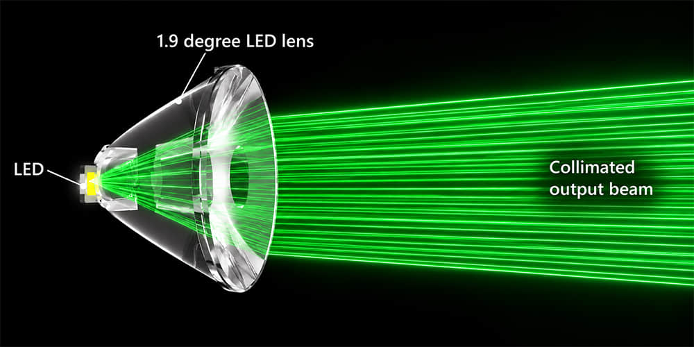
Beam angle generally describes the angular width of the central part of a light distribution. For a symmetrical directional luminaire, it is commonly defined as the angle between the two directions where luminous intensity falls to 50% of the maximum or center-beam intensity.
This is also called the full width at half maximum, or FWHM beam angle.
Consider an LED spotlight with a maximum luminous intensity of 20,000 candela:
- Maximum intensity on the beam axis: 20,000 cd;
- 50% intensity: 10,000 cd;
- The angle between the two 10,000 cd directions defines the beam angle.
If these two directions are located at −15° and +15° from the beam axis, the full beam angle is 30°.
The beam angle therefore describes the width of the brighter core. It does not mean that all light stops at 30°. Light continues beyond the 50% intensity boundary, normally with decreasing intensity.
The relationship among beam angle, field angle and center beam candlepower is illustrated in the U.S. Department of Energy’s CALiPER report on directional LED lamps.
What Is Field Angle?
Field angle describes a wider part of the distribution. It is the angle between the directions where luminous intensity falls to 10% of the maximum intensity.
Using the same fixture with a maximum intensity of 20,000 cd:
- Maximum intensity: 20,000 cd;
- 50% beam-angle threshold: 10,000 cd;
- 10% field-angle threshold: 2,000 cd.
If the 2,000 cd directions occur at −25° and +25°, the field angle is 50°, even though the beam angle is only 30°.
The Illuminating Engineering Society definition of field angle also notes that non-rotationally symmetrical beams are normally described in two planes at 90° to each other. This is important for oval, rectangular and asymmetric optical distributions.
Beam Angle vs Field Angle at a Glance
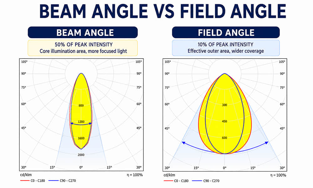
| Comparison | Beam angle | Field angle |
|---|---|---|
| Typical intensity threshold | 50% of maximum intensity | 10% of maximum intensity |
| What it describes | Brighter central beam | Wider visible distribution |
| Relative size | Narrower | Wider |
| Common use | Nominal beam classification and useful central coverage | Peripheral light, beam transition and spill evaluation |
| Intensity at boundary | Half of maximum intensity | One-tenth of maximum intensity |
| Usually shown on basic datasheets | Frequently | Less frequently |
| Enough for final lens selection? | No | No; both should be reviewed with complete photometric data |
The area between the beam-angle boundary and field-angle boundary is not completely dark. It contains lower-intensity light that affects visual beam size, edge softness, adjacent fixture overlap and light spill.
Why Two 30° LED Lenses Can Look Different
A nominal beam angle describes only one part of the distribution. Two lenses can both reach the 50% intensity threshold at ±15° while producing different intensity curves before and after those points.
Different Field Angles
Lens A may have a 30° beam angle and a 42° field angle. Lens B may have the same 30° beam angle but a 60° field angle.
Both lenses meet the basic 30° beam description, but Lens B continues sending measurable intensity much farther away from the central beam. On a wall or floor, Lens B can therefore appear to have a larger light pattern.
| Example optic | Beam angle | Field angle | Likely visual difference |
|---|---|---|---|
| Lens A | 30° | 42° | More compact overall light pattern |
| Lens B | 30° | 60° | Larger low-intensity perimeter and more visible spill |
The exact visual impression also depends on the shape of the intensity curve. Beam and field angles identify two thresholds but do not describe every point between them.
Different Center Beam Candlepower
Two 30° lenses can have different center beam candlepower, commonly abbreviated as CBCP. One may concentrate significantly more intensity around the optical axis even if both distributions cross the 50% threshold at the same angle.
For example:
| Example optic | Maximum intensity | 50% threshold | Nominal beam angle |
|---|---|---|---|
| Lens A | 20,000 cd | 10,000 cd | 30° |
| Lens B | 12,000 cd | 6,000 cd | 30° |
These lenses can share the same nominal beam angle while producing different center illuminance at the same distance.
If you need to distinguish lumens, candela and lux before comparing these figures, review Asahi’s guide to lumen, lux, luminous intensity and luminance.
Different Beam Profiles Inside the 50% Boundary
One lens may produce a relatively flat central distribution, while another has a narrow peak surrounded by lower intensity. Both can still cross the 50% boundary at the same nominal angle.
This affects how the light appears on the target:
- A peaked distribution may create a strong central hot spot;
- A flatter distribution may create more even illumination across the central area;
- Secondary intensity peaks may produce rings or multiple bright zones;
- An uneven distribution can make beam overlap more difficult.
This is why beam angle alone cannot be used as a complete description of optical quality.
Different Horizontal and Vertical Angles
A lens described simply as 30° may not be rotationally symmetrical. Its distribution could measure 30° in one plane and 45° in another.
Professional datasheets may express this as:
- 30° × 45°;
- 30° × 60°;
- C0-C180: 30°;
- C90-C270: 45°.
Oval and asymmetric lenses require information from multiple photometric planes. A single angle cannot describe their width, length, forward throw or direction of maximum intensity.
How to Calculate Beam Diameter
The approximate diameter of a symmetrical beam projected perpendicularly onto a flat surface can be calculated using:
Beam diameter = 2 × throw distance × tan (beam angle ÷ 2)
Where:
- Beam diameter is the approximate width between the 50% intensity boundaries;
- Throw distance is measured from the luminaire’s optical center to the target surface;
- Beam angle is the full angle, not the half angle.
Example: A 30° Beam at 10 Metres
Beam diameter = 2 × 10 × tan (30° ÷ 2)
Beam diameter ≈ 5.36 metres
If the same luminaire has a 50° field angle:
Field diameter = 2 × 10 × tan (50° ÷ 2)
Field diameter ≈ 9.33 metres
The brighter 50% beam is approximately 5.36 metres wide, but the 10% field extends across approximately 9.33 metres. This explains why a nominal 30° fixture can create a visible pool of light much larger than its calculated beam diameter.
Beam Diameter at Different Angles and Distances
| Beam angle | Diameter at 3 m | Diameter at 6 m | Diameter at 10 m |
|---|---|---|---|
| 10° | Approximately 0.52 m | Approximately 1.05 m | Approximately 1.75 m |
| 15° | Approximately 0.79 m | Approximately 1.58 m | Approximately 2.63 m |
| 30° | Approximately 1.61 m | Approximately 3.22 m | Approximately 5.36 m |
| 60° | Approximately 3.46 m | Approximately 6.93 m | Approximately 11.55 m |
| 90° | Approximately 6 m | Approximately 12 m | Approximately 20 m |
These are geometric calculations rather than guaranteed photometric results. They assume a symmetrical beam aimed normally at a flat target. Fixture tilt, asymmetric distribution, surface angle and optical distortion can change the actual footprint.
How to Calculate the Required Beam Angle
If the target width and throw distance are known, the approximate beam angle can be calculated by rearranging the beam-diameter formula:
Required beam angle = 2 × arctan (target width ÷ 2 × throw distance)
The calculation should be read as:
Required beam angle = 2 × arctan [target width ÷ (2 × throw distance)]
Example: Covering a 5 Metre Target from 8 Metres
Required angle = 2 × arctan [5 ÷ (2 × 8)]
Required angle ≈ 34.7°
A nominal 35° lens may therefore be a reasonable initial candidate. However, the calculation does not show whether the target receives enough lux, whether the beam edge is suitable or how much light extends beyond the target.
The next step is to check luminous intensity and the complete photometric distribution.
How Beam Angle Affects Illuminance
A narrower beam generally concentrates more of the available lumens into a smaller solid angle, potentially increasing candela and center illuminance. A wider beam distributes the output across a larger angular area.
For a point on a surface perpendicular to the beam axis, illuminance can be approximated using the inverse-square relationship:
Illuminance (lux) ≈ luminous intensity (candela) ÷ distance²
If a luminaire produces 30,000 cd on its beam axis:
| Distance | Approximate center illuminance |
|---|---|
| 5 m | 30,000 ÷ 25 = 1,200 lux |
| 10 m | 30,000 ÷ 100 = 300 lux |
| 20 m | 30,000 ÷ 400 = 75 lux |
This calculation applies to one direction and does not describe average illuminance across the complete beam. If the target surface is tilted relative to the incoming light, the angle of incidence also affects the result.
Why the Same Lens Can Produce a Different Beam
Beam and field angles are not determined by the lens name alone. The final distribution is produced by the interaction of the LED, lens, PCB and luminaire structure.
LED Light-Emitting Surface Size
An LED package such as 3535 or 5050 describes its approximate external dimensions, but it does not define the exact size and shape of its light-emitting surface.
When a lens developed around a smaller emitting surface is used with a larger source, the result may include:
- A wider beam;
- Lower peak candela;
- A softer cutoff or beam edge;
- More stray light;
- Changes in color distribution.
Two LEDs with the same package designation may therefore produce different photometric results under the same lens.
LED-to-Lens Distance
The lens is designed for a specific position relative to the LED emitting surface. If the LED sits too close to or too far from the intended optical reference position, the beam may become wider, narrower or distorted.
The distance can change because of:
- LED package height;
- PCB thickness;
- Lens support height;
- Gasket compression;
- Housing tolerances;
- Incorrect locating features.
Mechanical fit does not automatically prove optical alignment.
PCB and Optical-Center Alignment
In a multi-lens array, the LED pitch must match the lens-cell pitch. A small mismatch repeated across several LEDs can create increasing misalignment toward the end of the array.
The result may be a shifted beam, reduced symmetry, lower peak intensity or an asymmetric pattern that no longer points in the intended direction. Asahi explains these tolerances in more detail in How to Match an LED Lens to a PCB Layout.
Lens Material and Optical Surface
Changing the lens material or surface condition can affect transmission, refraction and visible beam quality. A frosted or micro-structured surface may soften LED images and improve mixing, but it can also change peak intensity and the transition around the beam edge.
Clear, textured and diffused versions of a similar lens geometry should not be assumed to have identical beam and field angles.
Protective Glass and Luminaire Structure
A cover plate, diffuser, housing edge or internal reflector can alter the distribution measured from the completed fixture. Even if the lens is unchanged, the complete luminaire may not reproduce the photometric curve of a lens tested in a different assembly.
How to Read Beam and Field Angles from a Polar Curve
A polar candela diagram plots luminous intensity at different angles. To estimate beam and field angles:
- Identify the maximum intensity in the relevant photometric plane.
- Calculate 50% of that value.
- Find the two angular directions where the curve crosses the 50% value.
- Measure the angle between them to obtain the beam angle.
- Calculate 10% of maximum intensity.
- Find the corresponding crossing directions to obtain the field angle.
For a symmetrical beam, the two directions may be equally positioned around the optical axis. For an asymmetric distribution, the maximum intensity may be shifted away from zero degrees, and the two boundaries may not be equal.
An IES file makes it possible to inspect the intensity values in multiple planes. Rather than duplicating the complete IES-reading process here, refer to Asahi’s guide on how to read an IES file for lens selection.
Why Beam Angle Alone Is Not Enough for Asymmetric Lenses
Beam angle is especially useful for symmetrical spot and flood distributions. It is less effective as a standalone description of roadway, aisle, wall-washing and other asymmetric optics.
An asymmetric lens may:
- Shift maximum intensity away from the optical axis;
- Project light farther in one direction;
- Restrict light behind the luminaire;
- Produce different widths in perpendicular planes;
- Create a rectangular, oval or irregular footprint.
Describing such a distribution as a single 60° beam can hide important information. It may be more appropriate to specify two angles, an IES distribution classification or a complete intensity diagram.
Common Mistakes When Comparing LED Lens Beam Angles
Comparing Nominal Labels Without Checking the Definition
One supplier may report the 50% beam angle, while another datasheet may use a wider visible-light boundary without explaining the intensity threshold. Confirm the measurement method before comparing the figures.
Assuming Light Stops at the Beam Boundary
A 30° beam does not mean zero light outside 30°. The field angle and complete polar curve show how much lower-intensity light continues beyond the central beam.
Using Beam Diameter as the Total Visible Spot
The calculated beam diameter represents the 50% intensity boundary when the conventional definition is used. The visually detectable light pattern may be much larger.
Comparing Different LEDs Under the Same Lens
A distribution measured with one 5050 LED should not automatically be applied to every 5050 LED. The emitting-surface size, height and primary optics can change the result.
Ignoring Horizontal and Vertical Planes
A lens may produce different angles in the C0-C180 and C90-C270 planes. One reported value cannot describe an oval or asymmetric beam.
Choosing Only by Lumens
Higher lumens do not guarantee higher target illuminance. Candela distribution and working distance determine how much light reaches a particular direction and surface.
Using a Lens-Level Test as a Finished-Luminaire Result
The PCB, protective cover, housing and assembly tolerance can change the distribution. Final approval should use the intended luminaire configuration.
A Practical LED Lens Selection Process
1. Define the Target Size
Record the width, length and orientation of the area that needs useful light. For vertical or inclined targets, use the dimensions of the actual task plane.
2. Define the Throw Distance
Measure from the luminaire’s optical center to the target, not simply from the floor to the mounting point. A tilted fixture may have different distances to the near and far sides of the target.
3. Calculate an Initial Beam Angle
Use the target width and throw distance to estimate the required 50% beam. Treat the result as an initial filter rather than final approval.
4. Define the Acceptable Field and Spill Area
Decide how much lower-intensity light may extend outside the central target. Applications near roads, windows or adjacent properties may require tighter spill control than general indoor lighting.
5. Check Center Intensity
Use candela data and distance to estimate center illuminance. Confirm that the result is neither too low nor excessively concentrated.
6. Match the LED and PCB
Confirm the exact LED part number, emitting-surface dimensions, package height, array pitch and LED-to-lens distance.
7. Compare Complete Photometric Data
Review the polar curves or IES files for beam shape, field angle, secondary peaks, asymmetry and high-angle intensity. Compare different lenses under the same lumen and installation conditions.
8. Test a Physical Sample
Install the lens over the intended LED and PCB. Measure the complete luminaire and visually inspect the projected beam for rings, hot spots, color separation and uncontrolled spill.
What to Ask a Lens Supplier
When requesting an existing optical lens, provide and confirm:
- Is the listed angle a 50% beam angle or another measurement?
- What is the field angle at the 10% intensity threshold?
- Are horizontal and vertical angles both available?
- Which LED brand and model were used for measurement?
- What LED-to-lens distance was used?
- Is the IES file based on a lens module or complete luminaire?
- What are the center or maximum candela values?
- Are the PCB drawing and lens drawing available?
- Does the lens use a clear, textured or diffused optical surface?
- Can a sample be tested with the customer’s LED and PCB?
Existing Lens Evaluation and Product Examples
Asahi Optics offers single LED lens options and multi-LED array lenses with narrow, medium, wide, oval and asymmetric distributions. The correct option should be selected according to both mechanical compatibility and complete photometric performance.
For example, the 2x4 LED Lens Narrow Beam 30° for Flood Lighting is a 50 × 50 mm, eight-cell PMMA array listed for 5050 LEDs. Its nominal 30° angle makes it an initial candidate for directional floodlighting, but the intended 5050 LED and PCB position must still be confirmed.
For wider coverage, the 60° Wide Beam 4x6 Flood Light Lens uses a larger 24-cell array and is listed for 5050 LEDs. Comparing this product with a 30° option should include target distance, luminaire lumens, candela distribution, required coverage and field spill—not nominal angle alone.
When a Standard Beam Angle Does Not Solve the Problem
A standard 15°, 30°, 60° or 90° lens may not be suitable when the project requires a special horizontal-to-vertical ratio, controlled field angle, sharp spill limit, unusual LED package or customer-specific PCB pitch.
In these cases, optical development may need to define more than a nominal beam angle. The project target can include:
- Beam angle in two photometric planes;
- Field angle and transition region;
- Required center intensity;
- Maximum intensity outside the target zone;
- Beam uniformity and edge appearance;
- Permitted rings, secondary peaks or color variation;
- Mechanical dimensions and LED-to-lens tolerances.
Asahi’s custom LED lens development can be considered when available optics cannot meet both the mechanical and photometric requirements. Existing lenses should normally be evaluated first to reduce development time and cost.
Conclusion
The difference between beam angle and field angle explains why two nominally identical LED lenses can perform differently. Beam angle normally describes the 50% intensity boundary of the brighter central beam, while field angle extends to the 10% boundary and includes more of the lower-intensity perimeter.
A 30° lens can therefore create a visible light pattern much wider than 30°. Two 30° lenses may also differ in field angle, center beam candlepower, beam uniformity, horizontal and vertical spread, or intensity outside the main beam.
For reliable selection, calculate the required beam diameter, check the target illuminance, review both beam and field angles, confirm the LED and PCB configuration, and validate the complete luminaire with photometric data and physical samples.
If you have a target beam diameter, working distance, LED model or reference IES file, request an existing lens recommendation from Asahi Optics. Our team can evaluate available lens options based on your LED, PCB, mechanical space and required light distribution.