Surgical lighting optics control how light from multiple LEDs reaches the operating field. Their purpose is not simply to create a bright spot, but to help an operating room light maintain useful illumination when part of the beam is obstructed by a surgeon’s head, hands or instruments.
A successful system depends on the combined performance of the LED source, secondary lens, PCB arrangement, luminaire geometry, thermal design and control system. Asahi Optics supplies precision LED lenses for manufacturers developing ceiling-mounted, mobile and compact surgical lighting systems.

What Is Surgical Lighting?
Surgical lighting refers to the specialized illumination used to support visual tasks during medical procedures. Depending on the product and its intended use, this may include ceiling-mounted operating room lights, mobile surgical lamps and compact procedure lights.
Unlike ordinary task lighting, an operating room luminaire must illuminate a defined working field from a practical working distance while clinicians and equipment move between the luminaire and the patient. The light field must therefore remain stable, usable and visually comfortable under conditions that are more demanding than general indoor lighting.
Modern LED surgical lights commonly use multiple individually controlled LEDs arranged across a circular or segmented lamp head. Each LED can be paired with a narrow-beam secondary optic and aimed toward the operating field. The overlapping beams form the complete illumination pattern.
Surgical lighting belongs to a broader range of medical lighting applications, but its optical requirements differ from dental lights, examination lights and general clinical luminaires. The lens should therefore be selected according to the intended luminaire rather than simply choosing the narrowest available beam.
What Lighting Problems Must an Operating Room Light Solve?
Maintaining Illumination When the Beam Is Obstructed
A single concentrated source can create a strong shadow when it is blocked. Surgical luminaires reduce this problem by projecting light from multiple positions around the lamp head. When one group of beams is obstructed, light arriving from other directions continues to illuminate the target.
This is often described as a “shadowless” effect, although no physical lighting system can eliminate every shadow. The practical objective is shadow dilution: reducing shadow contrast sufficiently to maintain visibility in the working field.
The effect depends on LED quantity, lens direction, lamp-head diameter, beam overlap and the position of the obstruction. Our article about the shadowless effect of surgical lights explains this multi-directional principle in greater detail.
Delivering Light at the Required Working Distance
The distance between the lamp head and operating field changes how a beam performs. A distribution that looks narrow and intense during a short-distance wall test may produce an unsuitable field when evaluated at the actual working distance.
A surgical light lens must capture light from the specified LED package and direct it toward the target without excessive spill. However, beam angle alone does not determine the final field diameter. LED emitting-surface size, lens-to-LED position, optical profile, luminaire aiming and working distance all affect the measured result.
For this reason, a 3°, 5° or 6° nominal lens should not be selected from the angle value alone. It must be tested with the intended LED and mechanical assembly.
Creating a Consistent Light Field
Poorly coordinated beams may form a bright center, visible rings, multiple hot spots or an uneven edge. These defects can remain hidden when one lens is evaluated individually but become obvious after dozens of optical channels are assembled into a lamp head.
The objective is to make the individual beams overlap as one usable field. Lens consistency is especially important because small variations in optical surface accuracy, LED position or mounting height can cause adjacent beams to land in different locations.
Supporting Deep-Cavity Visibility
Deep illumination cannot be judged from the maximum lux value alone. The luminaire must maintain a useful concentration of light along its working axis and through the intended depth range.
Narrow-beam optics can help direct more of the available flux into this region, but a narrower nominal angle does not automatically guarantee better cavity illumination. If the beams are aimed incorrectly or converge at the wrong distance, the system may produce a small peak near one plane and lose useful coverage above or below it.
The optical layout must therefore be designed around the complete three-dimensional illumination volume rather than a single measurement plane. This is particularly relevant to surgical light optical design for minimally invasive procedures.
How Optical Lenses Affect Surgical Lights
Beam Direction and Concentration
A raw high-power LED normally emits light over a relatively wide angular range. A secondary lens collects part of this output and redistributes it into a controlled beam. In a surgical lamp, each optical channel can then be positioned or tilted so that its beam contributes to the target field.
The lens profile affects the central intensity, beam width, edge transition and amount of spill light. The objective is not necessarily to maximize one value, but to create a distribution that works with the other optical channels in the array.
Beam Overlap and Field Uniformity
When multiple narrow beams overlap, their combined distributions determine the uniformity of the operating field. If the individual beams are too narrow, positioning errors may create gaps. If they are too wide, the lamp may waste light outside the useful field and reduce central illuminance.
Fixture designers must balance:
- Individual lens beam angle
- LED spacing and quantity
- Lens aiming direction
- Lamp-head diameter
- Working distance
- Target field diameter
- Required transition at the field edge
Simulation should include the complete LED array, not only one central lens. Mechanical tolerances should also be included because a theoretically uniform distribution can change after real components are assembled.
Optical Efficiency
High optical transmission helps more emitted light reach the target, but transmission percentage is only one part of efficiency. Light that passes through the lens but lands outside the useful surgical field does not contribute effectively to the application.
A suitable optic should combine material transmission with controlled distribution. This can help the luminaire reach its photometric target without relying only on higher LED current, which would increase electrical and thermal loads elsewhere in the system.
Color and Spectral Performance
A lens does not create the luminaire’s Color Rendering Index. CRI, R9 and correlated color temperature are primarily determined by the LED spectrum and the complete optical system.
The lens material should nevertheless provide stable visible-spectrum transmission and should not introduce unacceptable color variation across the beam. If warm-white and cool-white LEDs are used in the same lamp head, the arrangement and optical overlap must also be evaluated at each operating mode.
Because Asahi already provides detailed guides to CRI and R9 and correlated color temperature, those metrics are not repeated in detail here. For a surgical luminaire, they should be measured after the LEDs, lenses, protective cover and control settings have been integrated.
Translating Luminaire Targets into Optical Requirements
Before selecting a lens, the manufacturer should define measurable targets for the complete surgical lamp. These targets allow an optical engineer to determine whether an existing lens is suitable or whether a different distribution is required.
| System Target | What It Describes | How the Lens Contributes |
|---|---|---|
| Central illuminance (Ec) | Illuminance measured at the center of the light field under a defined test condition | Controls the concentration and direction of light delivered by each LED |
| Light-field diameter | The usable illuminated area at the reference plane | Affects individual beam width, edge transition and overlap |
| D10 and D50 | Diameters of the regions reaching defined percentages of central illuminance | Influences the shape and consistency of the combined field |
| Depth of illumination | The axial range over which useful illuminance is maintained | Helps determine beam convergence and longitudinal distribution |
| Shadow dilution | Performance when part of the light path is obstructed | Supports controlled overlap from multiple directions |
| CRI, R9 and CCT | Color reproduction and appearance of the complete luminaire | The lens should transmit the intended spectrum without unacceptable color shift |
| Thermal performance | Temperature behavior of LEDs, electronics, optics and housing | Lens material and spacing must be compatible with the measured operating temperature |
Central illuminance is measured in lux, while luminous intensity is measured in candela. These terms should not be treated as interchangeable. A more detailed explanation is available in our guide to lumen, lux, luminous intensity and luminance.
The final targets and test conditions should be taken from the product specification, applicable regulations and destination market. Surgical and diagnostic luminaires are covered by particular safety and essential-performance requirements in IEC 60601-2-41:2021. Compliance applies to the complete medical luminaire, not to an individual plastic lens, and should be verified by the finished-equipment manufacturer or an appropriate testing laboratory.
Information Required for Surgical Light Lens Selection
1. LED Package and Optical Source Data
The exact LED model is essential. Two LEDs described as “3535” may have different emitting-surface dimensions, dome structures and radiation patterns. These differences can change the beam produced by the same lens.
Please provide:
- LED manufacturer and complete part number
- Package drawing and LES dimensions
- LED radiation pattern or ray file, if available
- Required CCT and LED spectral options
- Operating current and expected junction conditions
2. Working Distance and Target Light Field
Specify the intended distance from the lens or lamp head to the reference plane. The required central illuminance, target field diameter and acceptable edge transition should be defined at this distance.
If the lamp has adjustable positioning or focus, provide the minimum and maximum operating distances. An optic selected for one fixed plane may not maintain the same field quality throughout a wider adjustment range.
3. Lamp-Head and PCB Geometry
The complete optical arrangement should include the diameter and shape of the lamp head, number of LEDs, PCB positions, lens spacing and the orientation of every optical channel.
A drawing should also show:
- Available lens diameter and height
- LED-to-lens reference position
- Permitted lens tilt or holder angle
- Protective cover position and material
- Mechanical fixing method
- Required assembly tolerances
4. Material and Operating Environment
PMMA and PC can both be used in optical assemblies, but their thermal, mechanical and chemical behaviors are different. Material selection should be based on measured temperatures, mechanical design, cleaning method and the environment inside the finished luminaire.
The lens should not be described as sterilization-resistant or compatible with a disinfectant unless the selected material and finished component have been tested with the actual chemical and exposure procedure.
5. Photometric Acceptance Criteria
Define how the prototype will be approved. Useful criteria may include the complete-luminaire intensity distribution, central illuminance, field diameter, axial illumination behavior, uniformity, obstruction tests and color measurements.
IES files and individual lens curves can support early comparison, but the approval decision should be based on testing the real LED, lens, holder, PCB, protective cover and luminaire structure.
Recommended Asahi Surgical Lighting Lenses
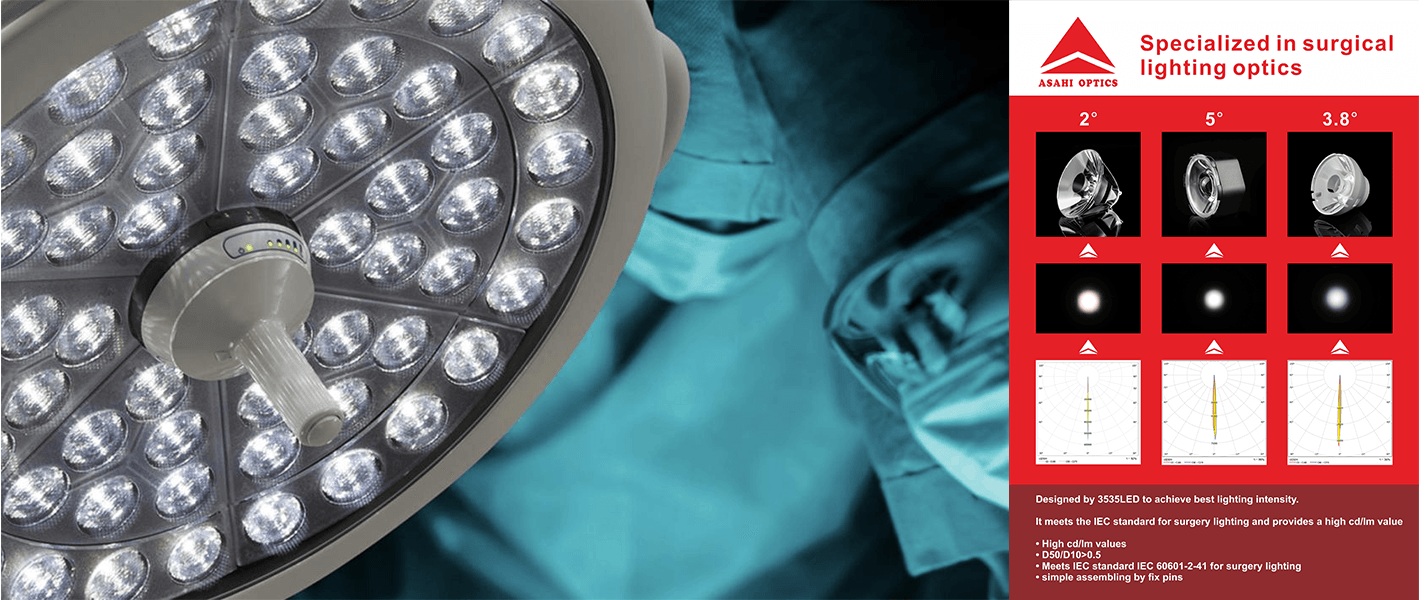
Asahi offers a dedicated Surgical Lighting Single Lens range with several diameters, nominal beam angles and LED compatibility options. The following products are practical starting points for prototype evaluation.
35mm Multi-Angle Surgical Light Lens
The AJS35D22H surgical light lens series provides nominal beam options of 3.8°, 4°, 6° and 15° within a common 35mm-diameter format.
- Model: AJS35D22H3.8G / 4G / 6G / 15G
- Diameter: 35mm
- Height: 23.33mm
- Material: PMMA
- Nominal transmittance: greater than 93%
- Listed LED compatibility: XPE-2, XPG-2, XPG-3 and XML
The multiple angle options allow a fixture developer to compare different combinations of concentration and field coverage without immediately changing the general lens envelope. For example, narrower versions may be evaluated for longer working distances, while the wider version may be useful where broader coverage is required.
The final beam must still be confirmed with the selected LED. Listed compatibility indicates a useful starting point, not identical performance across every LED package.
32.5mm 5° Compact Surgical Light Lens
The ASH31D19H5G 5° surgical light lens is a compact option for lamp heads in which multiple optical channels must be arranged within limited PCB space.
- Model: ASH31D19H5G
- Diameter: 32.5mm
- Height: 16.45mm
- Nominal beam angle: 5°
- Material: PMMA and PC construction
- Nominal transmittance: greater than 93%
- Listed LED compatibility: Cree XPE-2
Its compact dimensions can support higher optical-channel density, subject to the lamp-head structure, PCB spacing and thermal design. A physical sample should be installed at the specified lens-to-LED position before photometric performance is approved.
How to Evaluate an Existing Lens
Using an existing optic can shorten the development cycle when its mechanical dimensions and light distribution are reasonably close to the project requirements. A practical evaluation process includes the following steps:
- Check LED compatibility. Confirm the exact LED model, emitting surface and lens positioning.
- Check mechanical fit. Compare the lens diameter, height, holder design, PCB clearance and protective-cover position.
- Build one optical channel. Measure the beam produced by the actual LED and lens combination.
- Simulate the full array. Use the real lamp-head geometry and aiming angles to evaluate beam overlap.
- Build a functional prototype. Include the PCB, lens holders, cover and production-intent tolerances.
- Measure the complete luminaire. Verify photometric, color and thermal performance at the defined test conditions.
- Repeat obstruction tests. Confirm that the light field remains usable when representative optical paths are blocked.
An attractive wall spot is not sufficient evidence that the optic is ready for an operating room luminaire. The sample must be evaluated as part of the complete system and under its intended working geometry.
When Is a Dedicated Optical Design Needed?
An existing lens is normally the first option when it can satisfy the LED, space, beam and working-distance requirements. A dedicated optical design may be considered when:
- The specified LED does not match available lens platforms
- The required working distance creates an unsuitable field with standard optics
- The lamp-head geometry requires a special lens diameter or height
- Standard beams create rings, hot spots or excessive spill
- The project needs a specific overlap pattern across multiple optical zones
- The lens must integrate special locating, sealing or assembly features
For these cases, Asahi can provide a concise optical design and lens development service covering simulation, mechanical coordination, mold development, prototype evaluation and production. This capability is considered only after existing surgical-light optics have been reviewed.
Build the Surgical Light Around Verified Optical Data
Effective surgical lighting optics begin with a clear definition of the working distance, target field, LED package and lamp-head geometry. The correct lens is the one that helps the complete luminaire achieve controlled beam overlap, stable field coverage, useful depth and repeatable production performance—not simply the product with the smallest nominal beam angle.
To request an existing lens recommendation, send Asahi Optics your LED part number, PCB or lamp-head drawing, available lens space, working distance, target light-field diameter and photometric requirements. Our team can compare these inputs with available surgical lighting lenses and recommend suitable samples for testing.
Request an existing surgical light lens recommendation