
Construction site lighting must do more than make a jobsite appear bright. It needs to provide usable illumination on changing work surfaces, help workers identify hazards, support the safe movement of vehicles and equipment, and maintain sufficient visibility as a project progresses from excavation to structural work and interior finishing.
A construction site is rarely one uniform open space. It may include excavation areas, concrete placement zones, material storage areas, temporary roads, scaffolding, stairs, partially enclosed rooms and equipment maintenance points. Each area has a different mounting condition, target distance and visual task. As a result, one floodlight type or beam angle may not provide the best result across the entire project.
For manufacturers developing LED lights for construction sites, optical performance depends on the complete system: LED package, PCB layout, luminaire output, lens distribution, mounting height, fixture tilt and target distance. A high-power fixture with an unsuitable beam can create a bright hot spot while leaving adjacent work areas poorly illuminated. A correctly selected optical lens helps direct more of the available light toward the actual work zone.

What Is Construction Site Lighting?
Construction site lighting refers to fixed, temporary or portable lighting equipment used while construction work is in progress. It can support outdoor civil work, building construction, equipment operation, material handling, temporary access routes and indoor finishing before the permanent lighting system becomes available.
The terminology varies between markets. Building site lights is common in the United Kingdom and parts of Europe, while jobsite lighting and jobsite work lights are frequently used in the United States. Temporary lighting for construction sites may include lighting towers, mounted floodlights, portable work lights, festoon systems and temporary luminaires installed along corridors or work platforms.
These fixtures serve different optical purposes:
- Floodlights mounted above an open work area may need controlled medium or wide distribution.
- Lights positioned away from an excavation or vertical surface may require a narrower beam with stronger directional intensity.
- Portable work lights used close to workers need wide coverage with careful glare control.
- Temporary route lighting should provide continuous visibility without abrupt brightness changes.
- Lighting towers may use several independently aimed luminaires to cover separate working zones.
The selection of a construction site lighting lens should therefore begin with the work area and installation geometry rather than luminaire wattage alone.
Lighting Needs in Different Construction Areas
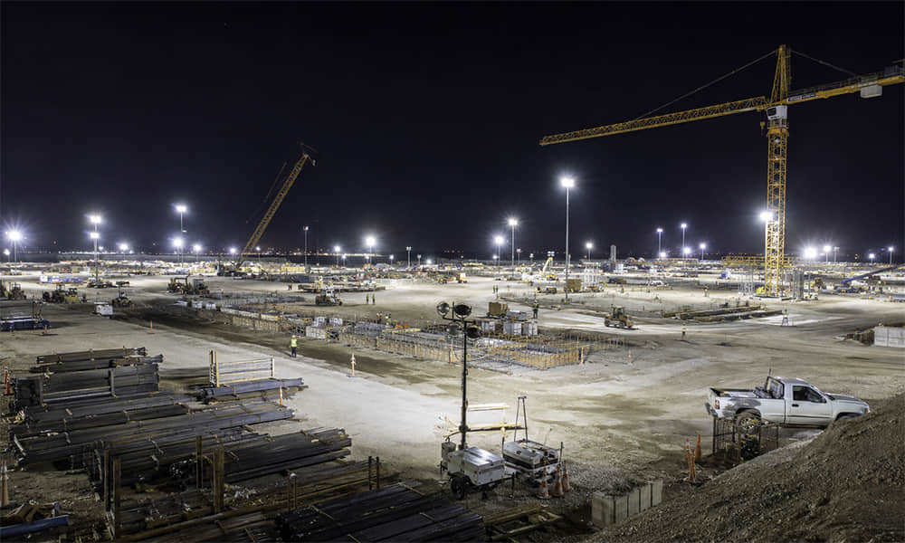
A practical lighting plan divides the jobsite into functional zones. Each zone can require a different balance of illuminance, beam direction, uniformity and glare control.
| Construction area | Main lighting requirement | Common optical concern |
|---|---|---|
| General outdoor work areas | Broad and reasonably uniform coverage | Dark gaps between floodlights |
| Excavation and concrete placement | Visibility at different ground levels | Deep shadows caused by terrain, machinery and formwork |
| Vehicle and equipment routes | Recognition of workers, barriers and moving equipment | Glare toward drivers and machine operators |
| Material storage and loading areas | Visibility of materials, labels and lifting points | Beam obstruction caused by stored materials |
| Scaffolding and vertical work surfaces | Light delivered onto vertical or inclined task planes | Worker shadows and insufficient vertical illuminance |
| Stairs, ramps and access routes | Continuous visibility along the full route | Dark corners and direct glare at eye level |
| Interior construction areas | General illumination plus local task lighting | Low mounting height and exposed bright light sources |
Open work areas usually need sufficient beam overlap to reduce dark zones. Excavations require additional attention because machinery, temporary structures and differences in elevation can block part of the light. Scaffolding and façade work must also be evaluated on vertical surfaces rather than only at ground level.
Temporary roads and vehicle routes present a different problem. A fixture tilted too far toward an approaching vehicle may produce strong glare even if it delivers adequate lux to the ground. The luminaire position and optical distribution should allow drivers to see workers and obstacles without placing the highest intensity directly in their line of sight.
Construction conditions also change throughout the project. New walls, equipment, scaffolding and stored materials alter the optical environment. A layout that worked during excavation may no longer provide suitable coverage during structural work or interior finishing. Temporary construction site lighting should therefore be reviewed at important project stages.
Common Construction Site Lighting Problems
Dark Zones Between Fixtures
Dark zones often occur when fixture spacing is determined only by wattage or maximum lumen output. Lumens describe the total amount of light emitted, but they do not show where that light reaches the work surface.
Two fixtures with the same lumens can produce very different results. A narrow-beam fixture may create higher center illuminance but limited lateral coverage. A wide-beam fixture may cover more ground but deliver insufficient illuminance at a longer distance.
Bright Hot Spots and Poor Uniformity
A bright hot spot can occur when the beam is too narrow for the mounting height or the fixture is positioned too close to the target. Increasing the luminaire power can make the center brighter without improving the surrounding area.
Better uniformity may require a different beam angle, adjusted fixture spacing, a revised aiming angle or additional luminaires. The most suitable solution cannot be determined from wattage alone.
Glare Toward Workers and Equipment Operators
Construction floodlights are often mounted on temporary poles, structures or tripods and tilted toward the work area. If the installation angle is excessive, workers can see the bright optical surface or LED array directly.
Glare is influenced by luminous intensity in the viewing direction, fixture height, aiming angle, distance, emitting-surface size and surrounding brightness. A lens can help control the distribution, but the final result also depends on the housing depth, shielding and installation position.
Spill Light Outside the Work Zone
Uncontrolled spill wastes available output and may affect nearby roads, buildings or completed parts of a project. A narrower beam is not always the solution. If it must be tilted aggressively to cover a large area, it can still produce glare and light outside the boundary.
A more suitable beam shape or a revised fixture position may control spill more effectively than simply reducing the nominal beam angle.
Construction Site Lighting Requirements
Lighting requirements depend on the country, project specification and type of work. For projects in the United States, OSHA standard 29 CFR 1926.56 provides minimum illumination intensities for construction areas while work is in progress. Contractors and lighting engineers should also review state requirements and project-specific documentation.
The following values are taken from OSHA 29 CFR 1926.56, Table D-3. OSHA expresses these requirements in foot-candles. The lux values are approximate conversions using 1 foot-candle = 10.764 lux.
| Construction area or operation | Minimum foot-candles | Approximate lux |
|---|---|---|
| General construction area lighting | 5 fc | Approximately 54 lux |
| Concrete placement, excavation, waste areas, access ways, active storage areas, loading platforms, refueling and field maintenance areas | 3 fc | Approximately 32 lux |
| Indoor warehouses, corridors, hallways and exitways | 5 fc | Approximately 54 lux |
| Tunnels, shafts and general underground work areas | 5 fc | Approximately 54 lux |
| Tunnel and shaft headings during drilling, mucking and scaling | 10 fc | Approximately 108 lux |
| General construction plants and shops | 10 fc | Approximately 108 lux |
| First-aid stations, infirmaries and offices | 30 fc | Approximately 323 lux |
These are minimum regulatory values for the listed U.S. construction areas. They should not be treated as universal recommendations for every country or visual task. Detailed assembly, inspection, electrical work or other demanding operations may require higher project targets.
A single lux reading also does not describe complete lighting quality. A site may reach the required average illuminance while still containing dark zones, strong shadows or excessive glare.
A professional evaluation may include:
- Average illuminance: the average lux level across the calculation area;
- Minimum illuminance: the lowest calculated or measured value;
- Uniformity: often evaluated by comparing minimum and average illuminance;
- Vertical illuminance: important for people, signs, machinery and vertical work surfaces;
- Glare risk: affected by intensity, observer position and fixture aiming;
- Spill and uplight: light delivered outside the intended construction zone.
Luminaire Parameters to Define Before Selecting a Lens
The optical lens is one part of the construction luminaire. A useful lens recommendation requires reliable information about the LED system, luminaire structure and installation.
Delivered Lumens and Luminaire Wattage
Wattage describes electrical input, not the amount or direction of light reaching the work area. Two 100 W fixtures may have different LED efficacy, driver losses, thermal performance and optical efficiency. Their delivered lumens and candela distribution can therefore be different.
Luminous efficacy, expressed in lumens per watt, is useful for comparing energy performance, but it still does not predict target lux without the light distribution and installation geometry.
As a simplified illustration, a luminaire delivering 20,000 lumens over an area of 400 m² has a theoretical ratio of 50 lumens per square metre. Actual illuminance will be lower or uneven because not all output reaches the calculation area. Utilization, distribution and maintenance conditions must be considered.
Mounting Height and Target Distance
Mounting height affects both coverage and illuminance. As the distance from the luminaire increases, the beam spreads over a larger area and illuminance at the target decreases.
The horizontal target distance is equally important. A fixture installed at the perimeter of a work area may need to project light forward, while one mounted above the center may use a more symmetrical distribution.
Useful project dimensions include:
- Height of the optical center above the target plane;
- Horizontal distance to the near and far edges of the work zone;
- Width and length of the required illuminated area;
- Available fixture tilt;
- Potential obstructions between the luminaire and target.
Fixture Tilt and Aiming Direction
Tilt changes where the highest-intensity part of a beam falls. It also changes how visible the bright luminaire surface is to workers. A narrow symmetrical lens normally requires more precise aiming, while a wider beam may tolerate more positional variation but provide less intensity at distance.
For a multi-head lighting tower, each luminaire should have a defined aiming point. Directing every head toward the same central area can create excessive overlap and leave the perimeter poorly illuminated.
LED Package and PCB Layout
An optical lens is developed around a particular LED light-emitting surface and mechanical position. A lens designed for a 3535 LED does not automatically produce the same beam over a 5050 LED. Even LEDs with the same package dimensions may use different emitting surfaces or dome structures.
For a multi-LED lens, confirm:
- LED brand and complete part number;
- Package dimensions and light-emitting surface;
- Number of LEDs under the lens;
- Center-to-center LED spacing;
- PCB dimensions and mounting holes;
- Distance between the LED emitting surface and lens reference plane.
If these parameters change, the measured beam angle, peak intensity and distribution uniformity may also change.
Environmental and Mechanical Requirements
Construction site work lights may be exposed to dust, rain, vibration, handling and elevated internal temperature. However, an optical lens alone does not give the complete luminaire an IP or IK rating.
An IP rating applies to the tested enclosure assembly, including the lens, gasket, housing, screws, cable entry and installation method. An IK rating must also be verified on the relevant product assembly.
Lens material selection should consider optical transmission, operating temperature, UV exposure, chemical compatibility and impact requirements. PC and PMMA offer different characteristics, so the suitable material depends on the luminaire and project environment.
How Optical Lens Parameters Affect Construction Lighting
Beam Angle
For a generally symmetrical beam, the beam angle is commonly measured between the directions where luminous intensity falls to 50% of the maximum intensity. A smaller angle concentrates more intensity into a narrower area, while a larger angle distributes light across a wider area.
The approximate beam diameter of a symmetrical luminaire aimed vertically at a flat surface can be estimated using:
Beam diameter ≈ 2 × mounting height × tan (beam angle ÷ 2)
| Nominal beam angle | Approximate diameter at 6 m | Approximate diameter at 10 m | General characteristic |
|---|---|---|---|
| 30° | Approximately 3.2 m | Approximately 5.4 m | Narrower and more concentrated |
| 60° | Approximately 6.9 m | Approximately 11.5 m | Balanced coverage and intensity |
| 90° | Approximately 12 m | Approximately 20 m | Wide coverage for shorter working distances |
These figures show geometric beam diameter rather than a guaranteed useful or uniform illuminated area. They assume a symmetrical beam, vertical optical axis and flat target plane. Fixture tilt, surface angle and real intensity distribution will change the footprint.
Luminous Intensity in Candela
Candela indicates how strongly a luminaire sends light in a particular direction. It is different from lumens, which describe total luminous flux.
A narrow-beam floodlight can have a higher peak candela than a wide-beam floodlight using the same luminous flux because more output is concentrated into a smaller angular area.
For a point on a surface perpendicular to the incident light, illuminance can be approximated by:
Illuminance (lux) ≈ luminous intensity (candela) ÷ distance²
For example, an intensity of 20,000 cd directed normally toward a point 20 metres away would theoretically produce:
20,000 ÷ 20² = 50 lux
This simplified calculation applies to one direction only. It does not describe average illuminance, beam uniformity or the complete work area.
Beam Shape and Intensity Distribution
Two lenses described as 60° can still produce different results. One may have a concentrated central peak, while another may provide a flatter distribution across the center of the beam.
When evaluating a flood light optical lens, check:
- Where the maximum intensity occurs;
- Whether the beam is circular, square, oval or asymmetric;
- How quickly intensity decreases toward the edge;
- Whether secondary peaks or rings are visible;
- How the distribution changes in different photometric planes;
- Whether adjacent beams can overlap without bright and dark bands.
A concentrated center may suit a distant task, while a smoother distribution can be more appropriate for general work areas where uniformity is more important than maximum center lux.
Optical Transmission
Lens transmission describes how much light passes through the optical material under stated conditions. It should not automatically be treated as the efficiency of the complete luminaire.
Final output can also be affected by LED temperature, driver performance, internal reflection, protective glass, optical texture, mechanical obstruction and assembly position.
A lens with high transmission can still produce an inefficient application result if it sends light outside the target area. Effective optics must combine appropriate transmission with useful light distribution.
LED-to-Lens Compatibility
The dimensions printed on an LED package do not fully describe its optical behavior. The relationship between the emitting surface and lens entrance geometry can affect beam angle, center intensity, symmetry, color-over-angle performance and stray light.
If a lens is listed for 3030, 3535 or 5050 LEDs, this is a starting point. The actual LED part number and PCB arrangement should still be checked before the lens is approved.
PC and PMMA Lens Materials
| Evaluation point | PMMA lens | PC lens |
|---|---|---|
| Optical performance | Commonly selected for high optical clarity and transmission | Can provide good performance when optical-grade material is used |
| Impact performance | More rigid and generally less impact-resistant than PC | Generally preferred where higher impact resistance is required |
| Temperature capability | Depends on material grade and actual lens temperature | Commonly considered for higher-temperature applications, subject to grade |
| Outdoor use | Review material grade and expected UV exposure | UV-stabilized grades may be required for long-term exposure |
The ambient site temperature is not the same as the operating temperature at the LED and lens. The actual component temperature should be measured after the luminaire reaches stable operation.
Matching Beam Angles to Construction Site Fixtures
The following guidance can be used for early-stage evaluation. Final selection should be confirmed using the intended luminaire output and mounting conditions.
| Lighting condition | Initial optical direction | Main reason | Important check |
|---|---|---|---|
| Higher mounting position or distant localized task | Approximately 30° narrow or medium-narrow beam | Maintains stronger intensity toward the target | Hot spots, aiming accuracy and glare |
| General outdoor work area at medium mounting height | Approximately 60° medium or wide beam | Balances coverage and intensity | Fixture spacing and beam overlap |
| Low-mounted portable work light | Approximately 90° or another suitable wide beam | Covers a wider nearby area | Direct glare and limited distant intensity |
| Long work zone or temporary route | Oval or asymmetric distribution | Places more light along the target zone | Orientation and end-of-route coverage |
| Vertical façade or scaffolding work | Controlled symmetrical or asymmetric beam | Directs light onto the vertical work plane | Worker shadows and viewing direction |
30° Optics for Focused Floodlighting
A 30° lens can be evaluated when a floodlight needs to deliver stronger intensity toward a relatively distant or restricted work zone. It may suit elevated mounting positions, façade work or areas that cannot be illuminated directly from above.
The narrower distribution requires more accurate aiming. If the fixture is too close to the target, the beam may create a small bright area with inadequate peripheral coverage.
60° Optics for General Work Areas
A 60° beam provides wider coverage than a 30° beam and can be evaluated for general work areas at moderate mounting heights. It may suit temporary area floodlights, material zones and lighting towers where each luminaire covers a defined section.
For lighting towers with several heads, overlapping controlled beams can provide better uniformity than directing every luminaire toward the same point.
Wide and Asymmetric Optics
Portable jobsite lighting is commonly installed closer to the work surface. A wider beam can cover more of the nearby area, but the fixture must prevent high-angle light from shining directly toward workers.
When a luminaire is installed only at the edge of a work zone, an asymmetric lens may redirect more output forward or along a defined axis. This can be useful for temporary access roads, building perimeters and long material-handling zones.
Using Photometric Data to Verify the Lens
Beam-angle calculations are useful for initial screening, but the final configuration should be checked with IES or LDT photometric data. An IES file records candela values in different directions and allows the complete luminaire to be tested in lighting software.
If you need an introduction to the format, read What Is an IES File?.
For a construction project, the simulation should use the actual work-zone dimensions, calculation surfaces, mounting heights, fixture positions and aiming angles. Review average and minimum illuminance, uniformity, vertical illumination, bright spots and light outside the target area.
The photometric file should represent the intended LED, PCB, lens and luminaire configuration. Changing the LED package, optical distance, cover or housing can change the measured distribution. The installed result should also be checked because new structures and materials can obstruct the light as construction progresses.
Recommended Lens Options for Construction Site Fixtures
Asahi Optics provides standard optical modules that can be evaluated for construction floodlights and temporary area luminaires. The Street and Area Lighting Lens range includes multiple array sizes, LED configurations and beam angles for different outdoor luminaire platforms.
2x4 LED Lens with a 30° Narrow Beam

The 2x4 LED Lens Narrow Beam 30° for Flood Lighting can be evaluated for focused construction floodlights requiring a compact optical module.
| Model | AZHB50D8LEDT30G |
|---|---|
| Lens layout | 2 × 4 array for 8 LEDs |
| Overall size | 50 × 50 mm |
| Height | 8.93 mm |
| Nominal beam angle | 30° |
| Material | PMMA |
| Specified transmittance | 93% |
| LED type listed for the product | 5050 LED |
The 50 × 50 mm module can support compact or modular luminaire designs, while its 30° distribution provides more directional control than a wide flood beam.
Before selection, confirm the exact 5050 LED, LED pitch, PCB locating structure and available lens height. The distribution should be checked with the intended LED because differences in the light-emitting surface can affect the measured beam.
4x6 LED Lens with a 60° Wide Beam
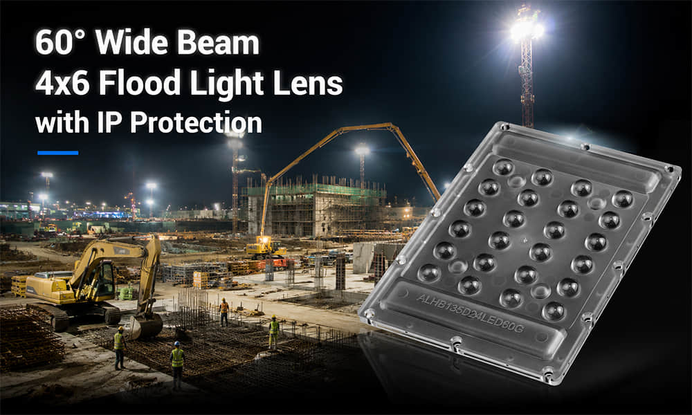
The 60° Wide Beam 4x6 Flood Light Lens with IP Protection can be evaluated for larger temporary area lights requiring wider coverage.
| Model | ALHB135D24LED60G |
|---|---|
| Lens layout | 4 × 6 array for 24 LEDs |
| Overall size | 135 × 100 mm |
| Height | 9 mm |
| Nominal beam angle | 60° |
| Material | PC-1250Z |
| Specified transmittance | Greater than 90% |
| LED type listed for the product | 5050 LED |
This product uses a larger 24-LED array and a 60° distribution for broader coverage. The PC material can be considered where the luminaire’s temperature and mechanical requirements make optical-grade PC appropriate.
The product incorporates an IP-protection-oriented lens structure. However, the IP rating of the completed construction light depends on the full enclosure, gasket compression, housing, cable entry, fasteners and assembly. The final luminaire must undergo the applicable ingress-protection test.
Comparing the 30° and 60° Options
| Selection factor | 30° lens | 60° lens |
|---|---|---|
| Target distance | Better starting point for a more distant or concentrated target | Better starting point for a nearer or broader target |
| Coverage | Narrower geometric footprint | Wider geometric footprint |
| Aiming | Requires more precise positioning | More tolerant of small aiming differences |
| Hot-spot risk | Higher if mounted too close or overlapped excessively | Lower center concentration, but distant lux may be insufficient |
| Initial application direction | Focused floodlight or elevated directional light | General temporary work-area floodlight |
A high-output 60° luminaire may deliver more distant illuminance than a lower-output 30° luminaire. Lens angle should therefore be compared together with luminaire lumens, candela distribution and working distance.
Checks Before Approving a Construction Lighting Lens
- Mechanical fit: confirm PCB dimensions, LED positions, lens height, mounting holes, locating features and sealing surfaces.
- LED compatibility: test the exact LED model and verify that every LED is centered under its optical cell.
- Thermal performance: measure the LED-board and lens temperature after stable operation.
- Photometric performance: review luminous flux, polar curves, beam angle, peak candela, symmetry and visible artifacts.
- Environmental performance: verify the complete luminaire through the required ingress, impact, vibration, UV or temperature tests.
- Application performance: use the final photometric file in the actual construction layout and check the relevant work surfaces.
Information Needed for an Existing Lens Recommendation
To recommend an existing LED lens for construction site lighting, Asahi needs information about the luminaire and application. Complete project data reduces the risk of selecting a lens that fits mechanically but does not provide the required distribution.
| Required information | Why it is needed |
|---|---|
| LED manufacturer and part number | Confirms emitting-surface geometry and optical compatibility |
| LED quantity and PCB drawing | Checks optical-cell pitch, mounting positions and available array formats |
| Luminaire drawing or available optical space | Confirms lens dimensions, height and mechanical interface |
| Expected luminaire lumens | Provides a basis for project photometric evaluation |
| Mounting height and fixture tilt | Defines working distance and beam footprint |
| Target area dimensions | Helps determine the required coverage in each direction |
| Required illuminance and uniformity | Defines the project performance target |
| Target beam or reference IES file | Allows available distributions to be compared |
| Environmental and material requirements | Supports PC or PMMA evaluation and enclosure planning |
If the project is still at the concept stage, the minimum useful information is the LED model, PCB layout, available lens size, target beam and expected mounting condition. These details can be used to screen existing optical modules before sample testing.
When an Existing Lens Is Not Enough
An existing product is usually the fastest route when its LED compatibility, array layout, mechanical size and photometric distribution match the fixture. Dedicated optical development may be considered when the PCB pitch is different, the luminaire requires a special beam shape, available optics cannot meet glare or spill-light targets, or the lens needs to integrate a customer-specific mounting and sealing structure.
For these projects, Asahi’s LED optical design and custom lens development capability can be reviewed after standard lens options have been evaluated.
Conclusion
Effective construction site lighting is not defined by wattage or maximum brightness alone. A dependable system must deliver sufficient light to the actual task, reduce dark zones, control glare and adapt to changing construction conditions.
The optical lens affects beam width, center intensity, distribution shape and the amount of light directed outside the work zone. A 30° lens may support a more focused or distant target, while a 60° lens may provide more practical coverage for a general temporary work area. Wider or asymmetric optics may be necessary for low mounting positions, long routes or perimeter installations.
Every selection should consider the complete optical system: LED package, PCB layout, lens position, luminaire output, mounting height, aiming angle and target geometry. Product specifications provide the starting point, while photometric simulation and complete-luminaire testing provide the evidence needed for final approval.
If you are developing construction floodlights, lighting tower heads, temporary area lights or professional jobsite work lights, request an existing lens recommendation from Asahi Optics. Send your LED model, PCB drawing, available optical dimensions, mounting conditions and target distribution so our team can evaluate a suitable standard lens for your fixture.