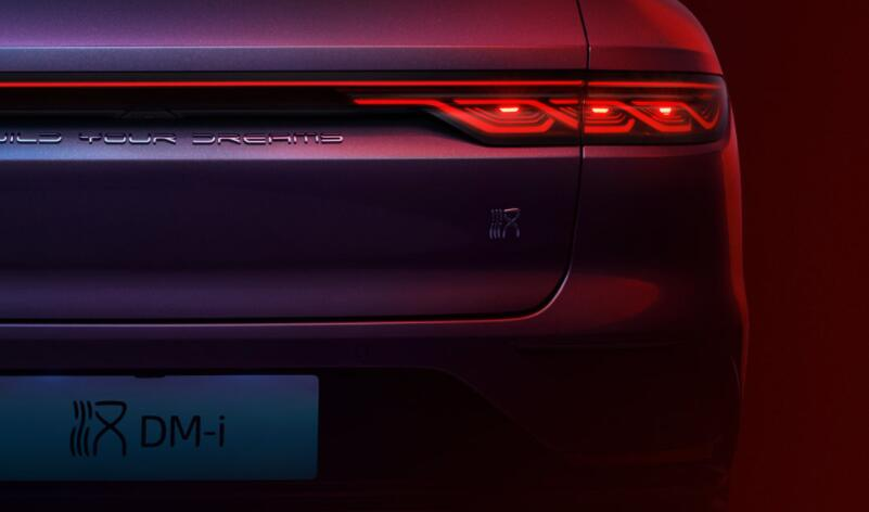
An automotive taillight must communicate clear signals to drivers and other road users behind the vehicle. It also contributes to the vehicle’s visual identity through illuminated lines, three-dimensional patterns and recognizable lighting signatures. Achieving both goals requires more than placing LEDs behind a red cover. The light must be collected, distributed and controlled by a properly designed optical system.
Automotive taillight optics may include individual LED lenses, lens arrays, reflectors, light guides, diffusers, thick-wall optics and micro-structured surfaces. These components help control luminous intensity, viewing-angle coverage, uniformity and the appearance of the lamp in both its illuminated and unlit states.
Asahi Optics supports manufacturers and lighting developers working on automotive lighting applications. This page explains how LED taillight optics work, what problems they must solve and which technical information is required to evaluate an existing optical solution or develop a dedicated lens.

What Are Automotive Taillight Optics?
Automotive tail light optics are the internal optical components that transform the output of one or more LEDs into the required rear-lighting signal. Their purpose is not simply to make the lamp appear brighter. They must place suitable luminous intensity in defined horizontal and vertical directions while maintaining the intended visual appearance.
It is important to distinguish an internal optical lens from the outer taillight cover. The outer cover is the visible transparent or colored part of the complete lamp assembly. It protects the internal components and contributes to vehicle styling. Inside the assembly, an LED tail light lens, light guide, reflector or diffuser performs most of the controlled light-distribution work.
A modern rear combination lamp may contain several lighting functions within one housing. Depending on the vehicle and target market, these may include:
- Rear position or tail light
- Stop or brake light
- Direction indicator
- Reversing light
- Rear fog light
- Side-marker or end-outline functions where applicable
These functions may share the same outer cover, but their required colors, intensity distributions and operating conditions are different. The optical system must preserve clear separation between them and prevent one illuminated area from making another signal difficult to identify.
Lighting Functions Inside an Automotive Taillight Assembly
Rear Position and Tail Light
A rear position lamp indicates the presence and width of the vehicle when viewed from behind. Its light should remain recognizable across the required viewing area rather than appearing bright only when observed directly on the optical axis.
In many current vehicle designs, the rear position function also creates the primary nighttime lighting signature. It may appear as a continuous line, ring, blade, segmented pattern or three-dimensional illuminated surface. The optic must create this appearance while still distributing light into the directions required for the complete lamp.
For this function, typical optical priorities include:
- Consistent visibility over the target horizontal and vertical angles
- Controlled brightness without distracting hotspots
- Uniform light extraction along long light guides
- A stable visual signature under different observation angles
- Acceptable efficiency at the selected LED current
A visually uniform surface does not automatically guarantee a suitable photometric distribution. Conversely, a lamp may meet individual intensity points while still showing unwanted LED images or dark bands. Both measured performance and visual appearance should therefore be evaluated.
Stop and Brake Light
The stop lamp informs road users behind the vehicle that the service brake has been applied or that the vehicle is intentionally slowing, according to the applicable system definition. It must be clearly distinguishable from the normal tail-light condition.
Some designs use separate optical areas for the tail and stop functions. Others use the same or partially shared illuminated area at different operating intensities. When functions share an aperture, the LED drive conditions and brake light optical lens must work together to create an unambiguous change in the signal.
Important design considerations include:
- Maintaining the intended intensity distribution in both operating modes
- Avoiding local saturation that makes only part of the lamp appear brighter
- Preserving uniformity as LED output changes
- Controlling optical leakage into neighboring lamp functions
- Managing temperature when LEDs operate at a higher current for the stop function
The required relationship between the tail and stop functions should be determined from the applicable regulation and customer specification. It should not be based on a universal brightness multiplier because lamp categories and target markets may impose different conditions.
Rear Fog Light
A rear fog lamp provides a more prominent rearward signal during conditions of seriously reduced visibility. Its optical purpose is to create a clearly visible signal in the required directions. It should not be described simply as “light that penetrates fog,” because its effectiveness depends primarily on the signal being detectable by other road users.
Rear fog lamp optics generally require controlled luminous intensity and reliable separation from adjacent rear-position or stop functions. Housing partitions, optical shields and dedicated lens regions may be used to prevent the stronger signal from spreading into unrelated areas of the rear combination lamp.
Other Functions in a Rear Combination Lamp
A reversing lamp may also be incorporated into the same assembly. Because it normally emits white light and performs a different function, the optical path and cover material must be coordinated to prevent color contamination or unwanted reflections inside the housing.
Direction indicators may use individual lenses, reflectors or light guides, including sequential systems that illuminate separate segments over time. Asahi discusses these requirements separately on its automotive turn signal optics page. The present page remains focused on tail, position, stop and related rear-lamp optics.
What Problems Must Automotive Taillight Optics Solve?
Visibility Across the Required Viewing Angles
A rear lamp is observed from different positions as vehicles change lanes, follow curves or approach at different heights and distances. A design that is bright directly behind the vehicle may lose intensity rapidly when viewed from the side or from a higher or lower angle.
The LED tail light light distribution must therefore be evaluated in both horizontal and vertical directions. Optical surfaces can redistribute light toward the required angular regions, but improving one direction may reduce the light available elsewhere. The target distribution should be defined before the lens geometry is selected.
Effective viewing-angle performance depends on several factors:
- The radiation pattern and emitting-area size of the LED
- The position of the LED relative to the lens or light-guide entrance
- The curvature and microstructure of the optical surfaces
- The clear aperture available inside the lamp
- Obstruction from bezels, shields and decorative components
- Refraction through the outer lamp cover
The outer cover should be included in the final optical evaluation. Even when it appears optically simple, its curvature, thickness, material and surface treatment can change the measured distribution of the complete assembly.
Uniform Illumination Without Visible Hotspots
LEDs are compact, discrete sources. When they are positioned directly behind a transparent surface, individual bright points may remain visible. Increasing the spacing between the LED and the cover can improve mixing, but many vehicle designs do not provide enough depth for this approach.
Automotive tail light uniformity can be improved through several optical methods:
- Individual lenses that expand or redirect each LED image
- Lens arrays that overlap the distributions from adjacent LEDs
- Diffusing textures that reduce visible source contrast
- Light guides that transport and extract light along a defined path
- Reflective mixing chambers that blend multiple sources
- Thick-wall optics that create controlled illuminated volumes
Uniformity must be balanced against efficiency. A strongly diffusing surface may hide LED hotspots, but it can also send light outside useful photometric regions. The preferred design creates the required visual continuity with the minimum necessary diffusion and optical loss.
Clear Separation Between Multiple Lamp Functions
Multiple rear-lighting functions are often positioned close together. Light can leak through housing gaps, reflective surfaces or shared optical components and make an inactive area appear partially illuminated. This optical crosstalk may reduce the clarity of the signal and affect the intended appearance.
A rear combination lamp optical system may control crosstalk through:
- Separate optical chambers
- Opaque shields or internal walls
- Controlled light-guide extraction regions
- Optical surfaces designed for specific angular ranges
- Careful selection of reflective and absorptive housing finishes
- Suitable spacing between LEDs and neighboring optical components
Crosstalk should be checked in simulation and on physical prototypes. Small gaps, glossy mechanical surfaces or changes in material color may create secondary reflections that are not obvious when each optical component is evaluated separately.
Creating a Recognizable Lighting Signature
The appearance of an automotive taillight is now an important part of vehicle identity. Manufacturers may request illuminated lines, floating shapes, layered patterns or three-dimensional depth effects that remain recognizable from different viewing positions.
The lighting signature must be developed together with the signal function. A shape that looks attractive in a rendering may become uneven when produced with real LEDs, or it may distribute too little light toward important photometric zones. Optical feasibility should therefore be evaluated before the styling surface becomes fixed.
For continuous signatures, the design may require a light guide with carefully distributed extraction features. For a three-dimensional signature, thick-wall optics or multiple illuminated layers may be appropriate. For a pixel-like appearance, direct-view lens arrays can preserve the intended separation between sources.
Fitting the Optics Into Limited Package Depth
Automotive rear lamps must fit between the vehicle body surface and internal structural components. The available space is shared by the LEDs, PCB, wiring, housing, vents, sealing interfaces, reflectors and decorative parts.
Reducing the distance between an LED and the optical surface can make source images more visible and increase sensitivity to positional errors. A long light guide may require additional space near the entrance to couple light efficiently. Thick-wall components may produce the desired appearance but require careful consideration of injection molding, weight and assembly.
The optical concept should therefore be selected according to the actual package rather than added after the mechanical layout has been completed.
Common Optical Solutions for LED Automotive Taillights
Direct-View LED Lenses
A direct-view system places a lens over each LED or uses a single molded array containing multiple optical cells. Each cell collects and redistributes light from its corresponding source.
This approach can be suitable for designs that intentionally show individual points or segments. It can also create a visually uniform panel when adjacent distributions are designed to overlap. The result depends on LED pitch, lens size, working distance and the angular distribution of each optical cell.
Advantages may include a short optical path, clear control of separate light-emitting zones and compatibility with modular PCB layouts. Potential challenges include visible brightness differences between LEDs, sensitivity to alignment and seams between adjacent distributions.
Light Guides for Continuous Lighting Signatures
An automotive light guide receives light through one or more entrance surfaces and transports it through the material, commonly using total internal reflection. Extraction features then redirect selected rays out of the guide to create a visible illuminated line or surface.
A successful automotive light guide design must control brightness along the complete path. If extraction is too strong near the LED, the entrance area appears bright while the far end becomes dark. If extraction is too weak, the guide may transport light efficiently but fail to produce the required visible signal.
Light-guide performance is influenced by:
- LED emitting area and radiation pattern
- Entrance geometry and coupling distance
- Guide cross-section and bend radius
- Surface quality and internal-reflection conditions
- Density, size and orientation of extraction features
- Material absorption over the optical path
- Mechanical supports that contact or obstruct optical surfaces
Curved light guides require particular attention. Rays may escape at tight bends, and the extraction pattern may need to change along the guide to compensate for variations in optical path and viewing direction.
Thick-Wall Optics
Thick-wall optics for automotive lighting use a relatively deep transparent component to transport and shape light within a visible three-dimensional form. The front, rear and internal surfaces can be designed to create different illuminated depths, reflections and signature effects.
This solution can provide strong visual identity and a premium appearance, but the optical and manufacturing design must be developed together. Large thickness transitions may increase molding difficulty, cooling time, shrinkage and the risk of sink marks or internal stress. The location of gates, ejector features and parting lines can also affect visible optical surfaces.
Simulation should account for the complete thick-wall geometry, material refractive index, surface finishes and neighboring reflective parts. A simplified analysis based only on the front face may not reproduce the actual illuminated appearance.
Diffusers and Micro-Optical Surfaces
An automotive taillight diffuser can reduce visible LED images and create a smoother luminous surface. Diffusion may be produced by material additives, surface texture or molded micro-optical features. Each method produces a different balance between appearance and light control.
Micro-prisms, pillow optics, Fresnel features and freeform surface structures can redirect light into selected angular zones rather than scattering it equally in all directions. This makes it possible to improve uniformity while preserving more useful intensity.
The selected texture should be evaluated for:
- Angular distribution
- Transmission and backscatter
- Visibility of the LED source
- Appearance when the lamp is switched off
- Mold replication and surface consistency
- Interaction with the outer cover
How the Optical Lens Affects Taillight Performance
Luminous Intensity Distribution
The geometry of a tail light lens determines how much light is sent toward different observation directions. Some surfaces broaden the LED distribution, while others concentrate light or redirect it asymmetrically. Complex optics may assign different surface regions to separate photometric zones.
Taillights are signal lamps rather than road-illumination lamps. Total lumens and a generic beam angle do not provide enough information to evaluate their performance. The relevant result is the luminous intensity distribution measured in candela across the required angular field.
During optical development, simulation can show whether the proposed design is likely to satisfy the target zones. Physical photometric testing is still required because LED output, molding variation, surface finish, assembly tolerance and the outer cover can change the final result.
Brightness Uniformity and Visual Quality
Uniformity can be evaluated through luminance images, calibrated photographs or measurement across selected regions of the emitting surface. Ordinary photographs taken with automatic exposure are useful for a general visual check but cannot reliably compare absolute brightness.
Common causes of uneven appearance include:
- LED pitch that is too large for the available mixing distance
- Incorrect lens-to-LED spacing
- Insufficient light-guide extraction at the far end
- Local losses around bends or mounting features
- Variations in LED output or color
- Optical obstruction from internal decorative parts
- Inconsistent molded textures
The required uniformity should be defined according to the intended styling. A deliberately segmented light should preserve its individual elements, while a continuous signature should minimize visible boundaries between sources.
Optical Efficiency
Material transmission is only one part of taillight efficiency. Light may also be lost at air-to-material surfaces, through absorption, at light-guide bends, behind opaque structures or in directions that do not contribute to the required signal.
An efficient optic places an appropriate proportion of the available LED light into the useful photometric field. This can reduce the electrical power required to reach the target, but the complete thermal and electrical system must still be evaluated.
Efficiency should not be increased by sacrificing glare control, signal uniformity or the required distribution. The goal is not simply the highest peak intensity; it is the correct intensity in the correct directions.
Color and Off-State Appearance
A rear lamp may use colored LEDs with clear optical components, white LEDs behind colored materials or other source-and-material combinations permitted by the project specification. The selected approach affects optical efficiency, color stability and the appearance of the lamp when it is not illuminated.
Material pigments and colored covers absorb part of the source spectrum, so color selection cannot be treated as having no effect on transmission. The source spectrum, material transmission curve and required signal color should be evaluated together.
Surface textures, metallic reflectors and dark decorative elements also affect the unlit appearance. These components should be included in the optical model when they are close to the active light path.
LED-to-Optic Alignment and Tolerance
The LED must remain at the position assumed in the optical design. Lateral displacement, height variation or angular tilt can reduce coupling efficiency and change the distribution.
In a lens array, misalignment may cause one cell to appear brighter or shift its beam relative to neighboring cells. In a light guide, displacement at the entrance may reduce the amount of light captured and create an uneven signature. In a thick-wall optic, a small source shift may alter the apparent depth or shape of the illuminated pattern.
Tolerance analysis should include:
- LED package and emitting-area position
- PCB thickness and flatness
- Solder-height variation
- Lens or light-guide locating features
- Holder and housing dimensions
- Outer-cover position
- Thermal expansion of relevant components
Reliable optical datums should be incorporated into the lens, holder and PCB design. Controlling the relationship between the LED and optic is more useful than applying unnecessarily tight tolerances to unrelated external dimensions.
Optical Parameters to Define Before Selecting a Taillight Lens
A lens recommendation should begin with the lamp function, LED and mechanical package. Selecting a component based only on its external dimensions is unlikely to produce a dependable result.
| Design input | Why it matters |
|---|---|
| Lamp function | Rear position, stop and rear fog functions have different optical targets and operating conditions. |
| LED model and emitting area | Source size, geometry and radiation pattern affect collection efficiency and the visible LED image. |
| LED quantity and spacing | These determine whether individual lenses, an array, a light guide or a mixing solution is practical. |
| Target intensity distribution | The required horizontal and vertical angles guide the optical surface design. |
| Available optical depth | Package depth limits the working distance, lens height, reflector size and light-guide entrance geometry. |
| Illuminated appearance | A point-source, continuous line, diffused surface or three-dimensional signature requires a different optical architecture. |
| Off-state appearance | Material color, surface texture and internal structures remain visible when the lamp is switched off. |
| Target market | The intended market determines the applicable regulations, lamp categories and validation methods. |
| Operating environment | Temperature, vibration, UV exposure and chemical contact influence material and mechanical decisions. |
These parameters allow the optical team to determine whether an existing component can support an initial prototype or whether the geometry and photometric target require a dedicated design.
Photometric and Regulatory Considerations
An automotive taillight should not be approved based only on its visual appearance or nominal LED output. The assembled lamp must be measured under the conditions required for its function and intended market.
For markets applying UNECE vehicle regulations, UN Regulation No. 148 for Light-Signalling Devices includes provisions for functions such as rear position lamps, stop lamps, direction indicators, reversing lamps and rear fog lamps. Installation requirements for lighting and light-signalling devices on the vehicle are addressed separately under the applicable vehicle regulations.
Projects intended for the United States should be evaluated against 49 CFR §571.108, FMVSS No. 108, together with the applicable referenced requirements and test procedures.
The relevant regulatory edition, lamp category and customer specification should be confirmed for each project. Requirements can differ according to vehicle type, lamp function, installation and market.
A typical validation plan may consider:
- Luminous intensity at specified test points or angular zones
- Signal color
- Visibility and apparent surface requirements where applicable
- Performance of combined or reciprocally incorporated functions
- Operation under specified voltage and environmental conditions
- Consistency between the left and right assemblies
- Effects of the outer cover and production components
The optical lens is one component within the lamp. Compliance claims must be based on the complete tested device or system, not on an isolated lens. Asahi therefore supplies optical performance information and development support without describing an individual unassembled lens as independently compliant with ECE, SAE or FMVSS requirements.
Material and Manufacturing Considerations
Choosing Between PC and PMMA
PMMA and polycarbonate are commonly considered for transparent optical components, but their suitability depends on where the part is installed and what it must withstand.
PMMA can provide high optical clarity and useful weathering performance in suitable grades. Polycarbonate may offer greater impact resistance and higher temperature capability, depending on the grade and application. Additives, pigments, coatings and molding conditions can change the performance of either material.
Material selection should consider:
- Optical transmission and refractive index
- Signal color and spectral transmission
- Continuous and peak component temperatures
- Impact and vibration exposure
- UV and moisture exposure
- Chemical compatibility with cleaners, adhesives and assembly materials
- Required surface hardness
- Part thickness and injection-molding feasibility
The outer lamp cover and an internal light guide do not necessarily require the same material. Each component should be evaluated according to its actual optical, mechanical and environmental role.
Injection Molding of Optical Features
An optical design must be transferable to a stable molding process. A surface that performs well in simulation may be difficult to reproduce if its features, wall thickness or part geometry are not compatible with tooling and material flow.
Manufacturing considerations include:
- Replication of micro-prisms and extraction textures
- Tool-polish requirements on transparent surfaces
- Parting-line and gate locations
- Draft and release of deep optical features
- Wall-thickness transitions
- Shrinkage, warpage and sink marks
- Flow lines and weld lines in visible regions
- Residual molding stress
These factors are especially important for long light guides and thick-wall lenses. Optical and tooling engineers should review the part before production tooling is finalized.
Environmental Validation
The expected vehicle environment can influence both optical output and mechanical stability. Temperature changes may alter LED output, material dimensions and the alignment between components. Vibration may affect locating features or electrical connections. UV exposure, humidity and chemicals may influence transparent materials and coatings.
The complete lamp manufacturer should define an appropriate validation plan based on the target market, OEM requirements and component location. Depending on the project, this may include thermal cycling, vibration, UV exposure, humidity, chemical compatibility and long-term operation.
Fixed environmental limits should not be assigned to every lens without confirming the material grade, part geometry, loading condition and test method.
Information Needed for an Automotive Taillight Optics Project
LED and PCB Information
The optical evaluation begins with the exact light source. LEDs with similar package dimensions can have different emitting areas, internal structures and radiation patterns.
Recommended information includes:
- LED manufacturer and complete part number
- LED datasheet and package drawing
- Emitting-area dimensions and optical center
- LED color or spectral information
- Operating current and expected temperature
- PCB drawing or 3D file
- LED coordinates, orientation and spacing
If several LED options are being considered, they can be compared during the concept stage. Changing the LED after the optical design has been finalized may require the distribution or coupling geometry to be re-evaluated.
Optical Target
The required lamp function and appearance should be clearly described. Useful inputs include:
- Rear position, stop, rear fog or combined function
- Target market and relevant lamp category
- Photometric table or customer intensity target
- Required signal color
- Desired illuminated shape and uniformity
- Reference lamp photographs or measurement data
- Requirements for the unlit appearance
A visual reference can help communicate the styling goal, but it does not replace numerical photometric requirements. When possible, both should be supplied.
Mechanical Package
The optical system must fit the real lamp assembly and remain correctly positioned in production. Recommended mechanical inputs include:
- Available 3D envelope
- Distance between the LED, optic and outer cover
- Housing and decorative-part geometry
- Lens or light-guide mounting method
- Reference datums and assembly direction
- Material or appearance restrictions
- Expected prototype and production volumes
Providing these inputs early reduces the risk of selecting a lens that produces a useful distribution but cannot be installed within the intended lamp package.
Automotive Taillight Optical Solutions from Asahi Optics
Existing Optical Solution Evaluation
Asahi Optics supplies and develops automotive lighting optics for multiple vehicle-lighting functions. For an automotive taillight project, an existing optical component may provide a practical starting point when its LED compatibility, dimensions and distribution are close to the project requirements.
The evaluation can consider direct-view lenses, lens arrays and other available optical structures. The lens should be tested with the intended LED and a representative PCB and housing. Results from an unrelated LED or an isolated lens cannot confirm the performance of the customer’s complete assembly.
Dedicated Taillight Lens and Light Guide Development
A dedicated optical design may be required when the project has a unique illuminated signature, limited package depth, unusual LED arrangement or specific photometric distribution that cannot be achieved with an available component.
Asahi can review the project through its custom optical lens design process. Depending on the requirements, the optical concept may use individual lenses, a multi-LED array, a light guide, a diffuser, thick-wall optics or a combination of these elements.
Development may include optical simulation, mechanical coordination, design-for-molding review and prototype evaluation. The exact scope should be defined according to the project stage and available technical inputs. The final lamp performance remains subject to verification using the production-representative assembly.
Develop the Taillight Around Its Signal, Appearance and Package
A successful automotive taillight must be visible in the required directions, communicate each function clearly and support the vehicle’s intended visual identity. These objectives depend on the complete system rather than the optical lens alone.
The LED, PCB, lens, light guide, reflector, diffuser, housing and outer cover should be developed as connected components. Early coordination between optical, mechanical, electronic and tooling teams makes it easier to balance uniformity, efficiency, styling, manufacturing and photometric performance.
To request an existing optical recommendation or discuss a new rear-lighting project, please contact Asahi Optics with the LED model, PCB layout, target lamp function, photometric requirements, available 3D space and desired illuminated appearance. These inputs allow the optical team to assess the project and recommend an appropriate next step.