
A TV backlight lens is an internal optical component used in direct-lit LCD display modules. Positioned over each LED, it spreads and redirects the light inside the backlight cavity so that the display panel receives a more uniform illumination field. The objective is not simply to increase brightness. The optical system must reduce visible LED hotspots, support consistent panel luminance, and work within the limited space available behind the LCD panel.
For TV and commercial-display manufacturers, the final backlight result depends on the complete optical stack: LED type, LED pitch, lens geometry, reflective backplate, diffuser plate, optical films, panel size, and backlight-cavity depth. A properly matched LED backlight lens helps turn discrete LED point sources into a smooth and usable illumination surface.
This page focuses on internal backlight optics for LCD TVs, commercial displays, digital signage, and direct-lit display modules. It does not cover RGB ambient LED strips installed behind a television, TV sync lighting accessories, consumer backlight kits, or replacement LED strips for television repair.
What Is a TV Backlight Lens?
LCD displays do not emit light by themselves. They require a backlight system behind the LCD panel to make images visible. In a direct-lit structure, multiple LEDs are placed behind the panel and each LED may use a TV backlight lens to distribute light over a wider area before it reaches the diffuser and LCD layers.
Without suitable optics, light from individual LEDs can remain concentrated near each source. This may create visible bright spots, dark areas between LEDs, uneven screen brightness, or a larger required distance between the LED board and the diffuser plate. A backlight lens helps create more overlap between neighboring LED beams so the display surface appears more uniform.
TV backlight lenses are commonly used in:
- Direct-lit LCD televisions
- Large-format LCD commercial displays
- Digital signage and information screens
- Interactive kiosks and control displays
- Direct-lit panel and backlit display structures
- Specialized display modules requiring controlled luminance distribution
A TV backlight lens is different from a TV backlight LED strip sold as a consumer accessory. The lens is part of the internal display optical system and must match the LED package, PCB layout, display structure, and required luminance performance.
How LED Backlight Lenses Improve Display Uniformity
An LED naturally emits light from a relatively small source area. In a display module, many LEDs must work together to illuminate one large panel. The role of display backlight optics is to expand, redirect, and blend the light from each LED before it reaches the visible display surface.
Expanding the Effective LED Coverage Area
A backlight lens can spread the light from one LED across a larger section of the cavity. This helps each LED contribute to a wider area of the diffuser plate rather than creating a concentrated bright point directly above the source.
The required distribution depends on LED spacing and optical distance. If the lens distribution is too narrow, the light may not reach far enough to overlap with neighboring LEDs. If it is too wide for the cavity and LED layout, the system may lose useful control or require different reflector and diffuser treatment.
Supporting Beam Overlap Between LEDs
Uniformity depends on how the light from adjacent LEDs combines. The goal is to create sufficient overlap at the diffuser or panel plane, reducing visible brightness variation between LED positions.
The correct overlap cannot be determined by lens angle alone. It must be evaluated together with LED pitch, lens height, backlight-cavity depth, diffuser material, reflector performance, and the dimensions of the active display area.
Reducing Visible LED Hotspots
A hotspot is a localized bright region that becomes visible on the display when the optical system does not sufficiently blend the output from individual LEDs. It may be caused by insufficient optical distance, a mismatch between lens distribution and LED pitch, an unsuitable diffuser structure, or inconsistent LED positioning.
A LCD backlight lens can help reduce hotspot visibility by spreading light more effectively before it reaches the optical films and display panel. The final result should always be confirmed using a complete display module, not an isolated lens test.
Improving Light Use Inside the Backlight Cavity
In a well-designed direct-lit module, the lens, reflector, and diffuser work together to direct more light toward the active display area. The lens does not work independently. Its distribution must support the reflective backplate and optical films used in the specific display design.
This system-level approach can help manufacturers improve luminance consistency without simply adding more LEDs or increasing cavity depth. The actual effect depends on the design of the complete module and should be verified by luminance measurements.
Common Direct-Lit LCD and Commercial Display Backlight Configurations
Direct-Lit LCD TV Backlights
A direct-lit LCD TV uses LEDs positioned behind the panel. Each LED may be fitted with a backlight lens that spreads the emitted light across the cavity. The optical target is to create a smooth luminance field while working within the available thickness of the television housing.
The most important inputs include LED package size, LED pitch, distance to the diffuser plate, panel size, target brightness, and the desired uniformity level. A change in any of these values can require a different lens distribution.
Commercial Displays and Digital Signage
Commercial displays may operate for long periods in retail spaces, transport hubs, public information systems, meeting rooms, and control environments. These applications often require stable brightness across a larger panel area, with particular attention to visible non-uniformity near panel edges and between LED positions.
For a larger display, the spacing and arrangement of LEDs become more important. The backlight lens must support the planned module layout and maintain a practical balance between optical performance, fixture thickness, thermal design, and assembly efficiency.
Large-Format Information Screens
Large LCD information displays require repeated optical performance across a broad active area. If the lens distribution, LED pitch, and backlight depth are not properly matched, the display can show clouding, uneven brightness bands, dark corners, or localized bright areas.
Optical testing should consider the entire active display region rather than only the center of the panel. Edge zones, LED-to-LED regions, and different viewing directions may reveal issues that are not visible in a small central measurement area.
Backlit Panels and Light-Box Structures
The same basic principle of spreading LED output can also be used in backlit panels and selected commercial light-box structures. However, these systems often have different cavity dimensions, graphics, diffuser materials, and target brightness requirements from LCD display modules.
For advertising light boxes and backlit signage, see our Billboard Lighting application page . That page focuses on the optical challenges of illuminated advertising panels rather than internal television and LCD backlight modules.
Backlight Problems That Optical Lenses Help Solve
Visible LED Hotspots
Visible bright points are one of the most common issues in direct-lit display backlights. They are more likely to appear when the distance between the LED and diffuser is limited, when the LED distribution is too concentrated, or when the diffuser and lens are not matched.
The lens helps redistribute the light over a larger area. However, a lens alone cannot guarantee the complete elimination of hotspots in every display. LED pitch, cavity depth, LED output, diffuser plate, reflective backplate, and assembly tolerances all influence the final appearance.
Dark Areas Between LED Positions
Dark areas can appear when the distribution from one LED does not overlap sufficiently with neighboring LEDs. This can create a visible grid or brightness variation across the display, especially in thin modules with limited mixing distance.
A suitable LED TV backlight lens must be selected according to the actual LED pitch. The objective is to create enough overlap at the relevant optical plane while keeping the design compatible with the available module thickness.
Uneven Brightness in Thin Backlight Cavities
Thin displays offer less space for light to mix naturally. When the backlight cavity becomes shallower, the optical lens has less distance to spread light before it reaches the diffuser plate and panel.
Wide-angle backlight optics can be useful in these structures because they distribute light laterally earlier in the cavity. The final lens geometry must still be matched to the module depth and LED layout. An overly wide distribution is not automatically the best choice for every thin display.
Brightness Variation Near Panel Edges
Edge brightness depends on more than the lens. LED placement near the perimeter, reflector geometry, panel frame structure, diffuser position, and the available cavity space all affect the result.
During development, luminance mapping should include the center, edge, corner, and LED-to-LED regions. This allows the engineering team to identify whether the issue comes from the lens distribution, LED layout, reflective materials, mechanical tolerance, or the complete optical stack.
Color-Over-Angle and LED Consistency
LED binning, phosphor characteristics, optical films, diffuser materials, and viewing angle can all influence color appearance across a display. The lens can affect the angular distribution of light, but it does not independently determine color consistency.
For this reason, backlight optical development should evaluate luminance and color behavior using the actual LED source and the full display module. A clear optical performance target helps avoid assigning all visual issues to one component.
Key Parameters for Selecting a TV Backlight Lens
The following information helps identify a suitable existing TV backlight lens or determine whether further optical evaluation is required:
| Project Input | Why It Matters |
|---|---|
| LED manufacturer, model, and package | Determines the LED emitting area, lens compatibility, and optical alignment requirements. |
| LED emitting-surface dimensions | Affects lens collection efficiency, beam distribution, and hotspot control. |
| LED pitch | Defines how far the light must spread to overlap with adjacent LEDs. |
| Panel size and active display area | Influences LED quantity, module layout, and edge-lighting requirements. |
| Backlight-cavity depth | Limits lens height and available optical mixing distance. |
| Target luminance | Helps determine LED output, optical efficiency, and overall backlight configuration. |
| Uniformity target | Provides the performance requirement for center, edge, and LED-to-LED brightness variation. |
| Diffuser plate and optical films | Work with the lens to blend light and control visible LED points. |
| Reflective backplate structure | Affects internal reflection, light utilization, and perimeter brightness. |
| Lens mounting method | Determines locating pins, clips, adhesive methods, and PCB compatibility. |
| Thermal and reliability requirements | Supports appropriate material and structural evaluation for the display module. |
How to Improve Uniformity in Thin Direct-Lit Backlight Modules
Match Lens Distribution to LED Pitch
LED pitch and lens distribution must be selected as a pair. If the pitch is large but the lens does not spread light far enough, the diffuser may show dark areas between LEDs. If the distribution is much wider than the cavity and optical stack require, it can create other control challenges.
The recommended approach is to evaluate a proposed lens with the actual LED board and intended pitch. Optical simulation and prototype luminance measurements can then confirm whether adjacent light fields overlap correctly.
Use Available Optical Distance Effectively
The optical distance is the space between the LED/lens system and the diffuser or panel layers. In shallow modules, there is less distance for light from adjacent LEDs to blend naturally.
Backlight lens geometry can help distribute light laterally within this limited space. The selection should consider both optical performance and the mechanical height available for the lens, PCB, reflector, diffuser plate, and panel frame.
Evaluate the Full Optical Stack
A direct-lit backlight module is a system. The lens must work with the LED, reflective backplate, diffuser plate, prism films where used, LCD panel, and mechanical cavity. Changing one component can change the overall luminance map.
For example, changing the diffuser material or reducing cavity depth may require a different lens distribution even if the LED model and pitch remain unchanged. Testing the complete optical stack is more meaningful than testing a lens by itself.
Verify with Luminance Mapping
Luminance mapping measures brightness at multiple positions across the active display area. It helps identify center-to-edge variation, corner performance, LED-to-LED dark zones, and localized hotspots.
A complete test plan should define the measurement grid, target luminance, uniformity requirement, and viewing conditions before evaluating the final module. This provides a practical basis for comparing lens options and confirming production readiness.
Recommended TV Backlight Lens Options from Asahi
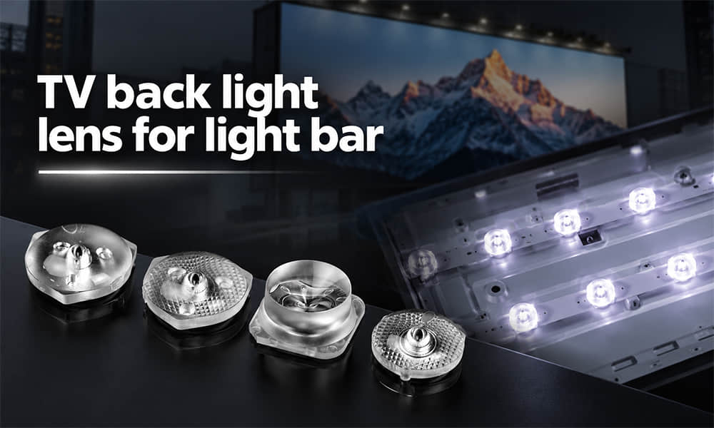
Asahi provides backlight optical components for LED display modules. The TV Backlight Lens Collection can be used as the starting point for projects requiring direct-lit LCD backlight optics.
Backlight Lenses for Direct-Lit LCD Modules
Direct-lit TV and LCD modules require lenses that match the LED package, pitch, and cavity depth. Existing lens options should be evaluated according to the desired coverage area of each LED and the required overlap at the diffuser plane.
Before selecting a model, the display manufacturer should compare LED compatibility, lens dimensions, mechanical locating features, and the expected luminance distribution in the final module.
Wide-Angle Backlight Optics for Thin Display Cavities
Wide-angle optics can be considered when the display cavity has limited mixing distance and the backlight system needs earlier lateral spreading of LED output. These designs are particularly relevant for thin direct-lit modules where visible LED points and dark gaps are major development concerns.
The appropriate lens must be confirmed against the complete display stack. A wide distribution should not be selected only because the module is thin; LED pitch, diffuser design, reflector performance, and target uniformity remain essential selection inputs.
When an Existing LED Backlight Lens Does Not Match the Module
An existing lens may not be suitable when the LED package, LED pitch, PCB hole pattern, cavity depth, or fixing method differs from the available optical platform. Further evaluation may also be needed when the prototype shows visible hotspots, dark regions, poor edge uniformity, or an unsuitable lens height for the intended display structure.
In these cases, the first step is to review the LED datasheet, PCB layout, panel dimensions, optical distance, diffuser structure, reflective backplate, target luminance, and uniformity requirement. If an existing product cannot meet the project requirements, Asahi can review the module through its custom LED lens development service .
Request an Existing TV Backlight Lens Recommendation
To request an existing TV backlight lens recommendation, please provide:
- LED manufacturer, model, package, and datasheet
- LED emitting-area dimensions
- PCB layout, LED pitch, and mounting-hole positions
- Panel size and active display area
- Backlight-cavity depth and available lens height
- Diffuser plate, optical-film, and reflector details
- Target luminance and uniformity requirement
- Existing luminance map, panel image, or test result if available
- Lens mounting method and mechanical drawing requirements
- Thermal, reliability, and material requirements
With these inputs, Asahi can compare suitable existing LED backlight lens options and recommend a practical starting point for module prototyping and optical validation.