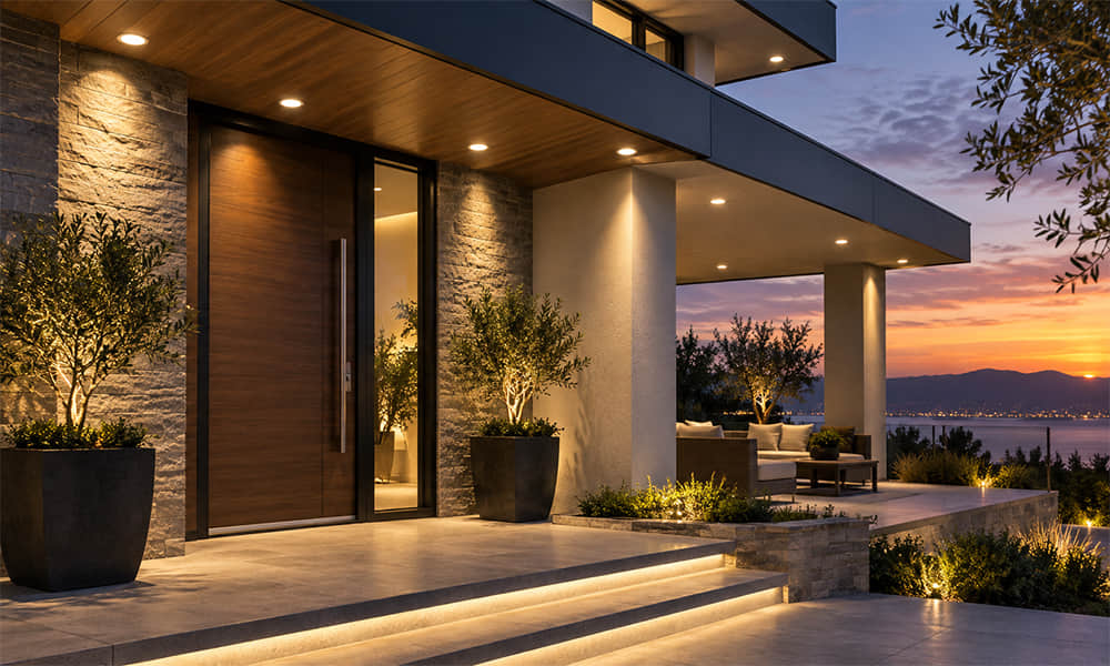
Luminous intensity is the amount of visible light emitted in a specified direction. It is measured in candela (cd). For an LED luminaire, candela helps explain whether light will reach a distant target, create a concentrated spot, spread evenly across an area or produce excessive glare.
This matters because two luminaires can have similar lumen output but very different lighting results. The difference often comes from how the LED light is distributed by the optic, not from the LED’s total lumens alone.
Luminous Intensity, Lumen, Lux and Luminance
| Quantity | Symbol | Unit | Practical Meaning |
|---|---|---|---|
| Luminous Flux | Φ | Lumen (lm) | Total visible light emitted by the source |
| Luminous Intensity | I | Candela (cd) | Light emitted in one specified direction |
| Illuminance | E | Lux (lx) | Light arriving on a target surface |
| Luminance | L | cd/m² | Light emitted or reflected from a surface in a specified direction |
These values describe different stages of the same lighting system. An LED produces luminous flux. A lens redistributes that flux into an intensity distribution. The intensity distribution and mounting distance determine illuminance on the target. The surface condition and viewing direction then influence luminance.
What Luminous Intensity Means in Photometry
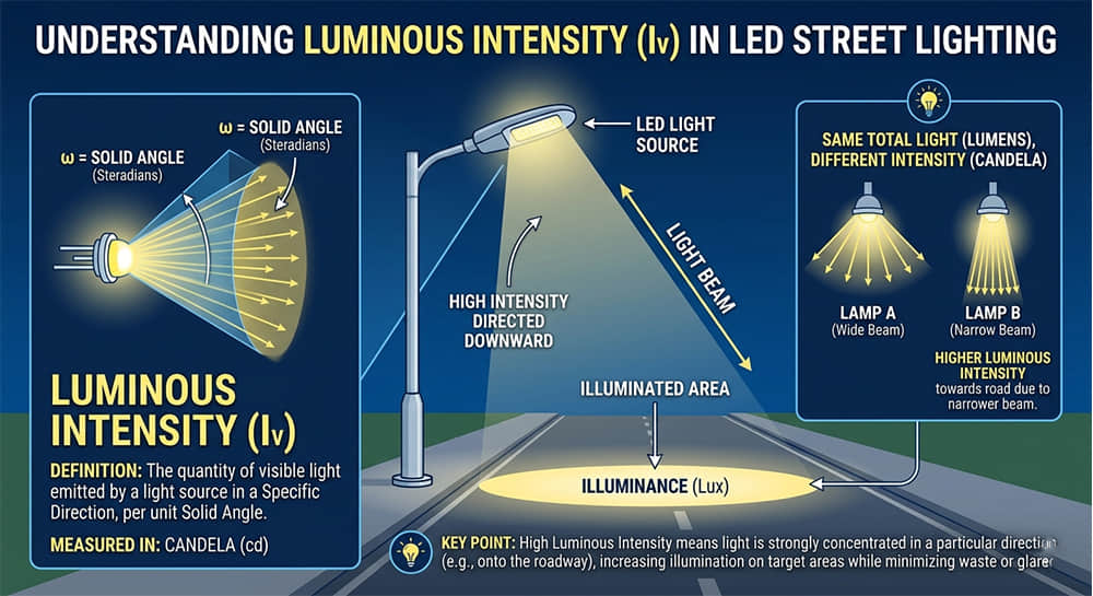
Luminous intensity is expressed as:
I = dΦ / dΩ
Where I is luminous intensity in candela, dΦ is luminous flux in lumens and dΩ is the solid angle in steradians. In practical terms, candela indicates how concentrated the available light is in a given direction.
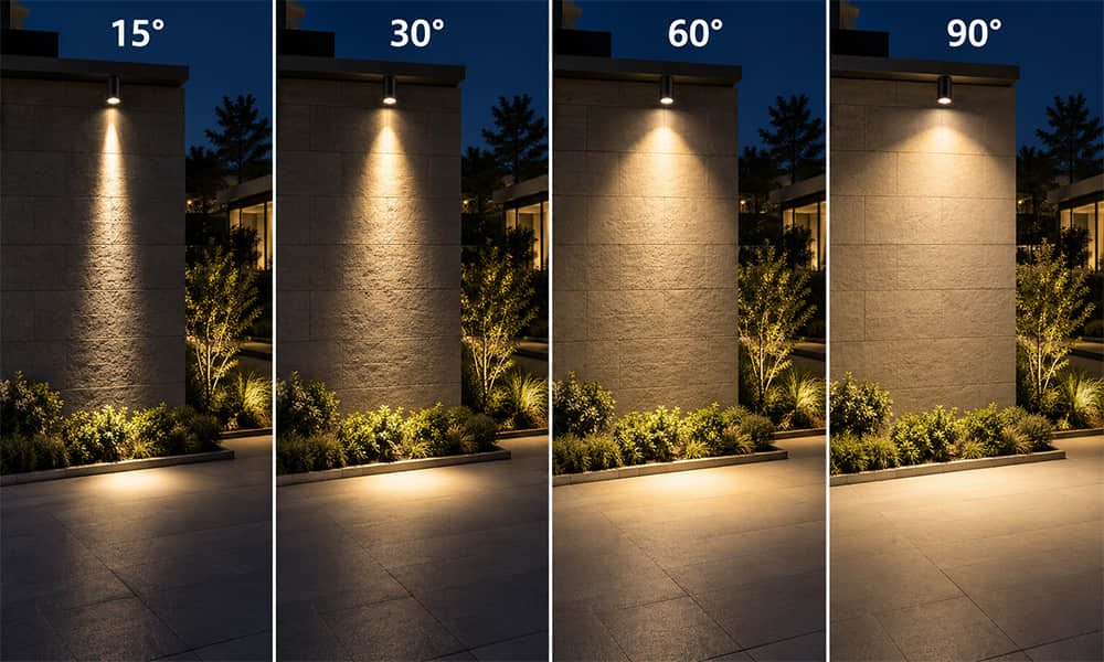
A narrow optic can direct a larger portion of the available light toward a smaller angular area, increasing candela near the optical axis. A wider optic distributes light over a larger angular area, generally reducing peak candela while increasing coverage.
This does not mean that a narrow beam is automatically better. A narrow distribution may be correct for a distant sign, a spotlight or a high-mounted fixture, but unsuitable for a wide work area, roadway or wall where uniform coverage is required.
Why Lumens Cannot Be Converted to Candela by One Fixed Number
A common question is: “How many candela is 1,000 lumens?” The correct answer is that there is no fixed conversion. Candela depends on how the lumens are distributed, not only on the total amount of light produced by the LED.
For an idealized uniform cone, narrowing the beam increases the intensity within that cone. Real luminaires are more complex. They have non-uniform distributions, optical losses, edge falloff, LED source-size effects, lens surface tolerances and fixture components that influence the final result.
Therefore, a nominal beam angle should never be treated as a direct candela value. The proper comparison is the measured candela distribution of the complete luminaire, shown in an IES file, LDT file or polar curve.
Beam Angle Is Not a Hard Edge
In many LED product specifications, beam angle is defined by full width at half maximum (FWHM). This is the angle between the two directions where luminous intensity falls to 50% of the peak value.
A 30° FWHM beam does not mean that all light stops exactly at 30°. It means the intensity has fallen to half of its maximum at that angular position. Light may still exist outside the stated beam angle, and its amount can affect glare, spill light and uniformity.
For this reason, two products both described as 30° can perform differently. One may have a tight central peak with fast edge falloff. Another may have a broader shoulder distribution and more spill light outside the FWHM angle.
For a practical example of how a wider nominal angle changes light coverage, see our guide to 90 degree LED lens light coverage.
Why the Same Lens Can Produce Different Results with Different LEDs
An LED lens is not evaluated independently from its source. The apparent size, shape and position of the LED emitting surface affect the final beam distribution.
A 30° lens specified with one 3535 LED may not remain a 30° lens when used with a larger emitting surface. The larger source can broaden the resulting distribution, lower peak intensity and change the beam edge. The same effect can occur when the LED-to-lens distance, PCB thickness or lens mounting height changes.
This is one reason why a lens should be checked with the intended LED model and PCB layout. A product drawing may confirm mechanical compatibility, but it cannot by itself confirm the final photometric result.
A TIR optics lens, for example, can direct light through refraction and total internal reflection. Its actual candela distribution still depends on the LED source, the lens position, the holder and the fixture structure around it.
How Candela Becomes Lux on the Target
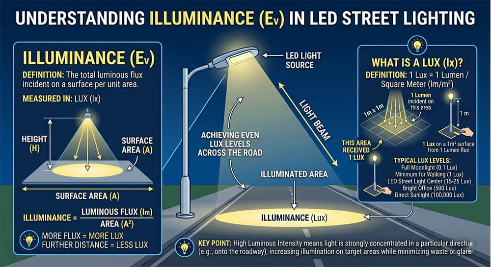
For a point-like source aimed at a surface, illuminance can be estimated using the inverse-square law:
E = I cos α / d²
Where E is illuminance in lux, I is luminous intensity in candela, d is the distance from the source to the target in meters and α is the angle between the incident light and the surface normal.
When light reaches the target perpendicular to the surface, α is 0° and cos α equals 1. As the beam reaches the target at a more oblique angle, illuminance decreases. This is particularly important for street lighting, wall washing, perimeter lighting and tilted luminaires.
The formula is useful for early evaluation, but it is still an approximation. A real fixture is not a perfect point source, and actual illuminance depends on the full candela distribution, fixture tilt, mounting height, spacing, target geometry and reflections from nearby surfaces.
Peak Candela Is Not the Same as Good Lighting Performance
Peak candela, sometimes described as center beam candlepower (CBCP), is useful when comparing focused luminaires. However, it only describes the strongest point in the distribution. It does not show whether the beam covers the target evenly or whether it creates unwanted glare outside the target area.
For a narrow spotlight, high center intensity may be the correct result. For a road, warehouse aisle, parking area or facade, an excessively concentrated peak can create a hotspot while leaving adjacent areas underlit.
Good lens selection balances several requirements at the same time: target illuminance, beam shape, coverage, spacing, uniformity, glare control and spill light. Candela is an important input, but it should be interpreted as part of the full distribution rather than as a stand-alone quality score.
How Luminous Intensity Is Measured
Candela is not a fixed value of the LED chip or the lens alone. It is measured from the assembled optical system:
- LED model, bin and drive current
- PCB layout and LED location
- Lens geometry, material and lens-to-LED distance
- Holder, housing, cover and mechanical alignment
- Photometric measurement of the completed luminaire
A goniophotometer measures the fixture at many vertical and horizontal angles. The data can then be provided as an IES file, LDT file or polar curve. This is the data needed to see how intensity changes from the beam center to the edge, rather than relying on one peak candela value.
When comparing lens options, verify the LED type, current, PCB configuration, test setup, lens material and fixture structure used for the photometric result. If these conditions differ from the planned luminaire, the IES result should be treated as a reference rather than a final prediction.
For a detailed explanation of this workflow, read how to read an IES file for LED street light lens selection.
What to Check When Comparing Lens Photometric Data
When reviewing candidate optics, do not compare beam angle or peak candela alone. Check the complete set of information available for the tested configuration:
- LED model, package size and drive current
- PCB layout, LED pitch and optical-center alignment
- Lens material, lens height and holder configuration
- Peak intensity and candela distribution at different angles
- FWHM beam angle and the shape of the beam edge
- Total fixture flux and estimated optical efficiency
- Target distance, mounting height, aiming direction and coverage requirement
- Required average lux, minimum lux, uniformity and glare limits
This comparison method is more reliable than selecting a lens only because it has a stated 15°, 30° or 60° beam angle. It also helps identify whether the luminaire needs a narrow, flood, elliptical or asymmetric distribution.
Applying Candela Data to Outdoor Lighting
For street and area lighting, the main question is rarely “Which lens has the highest candela?” Instead, the important question is whether the measured distribution places light across the required roadway, parking area or pedestrian zone with appropriate uniformity and limited unwanted spill.
An asymmetric optic may send more light forward across a road while controlling light behind the pole. A wide area optic may suit a parking lot or open space. A narrow distribution may be suitable only where mounting height, target distance and beam overlap have been carefully evaluated.
See our street and area lighting lenses for optical module options used in roadway and area-lighting fixtures.
Request an Existing Lens Recommendation
For a meaningful lens recommendation, send the LED part number and datasheet or ray file, PCB drawing, luminaire drawing or available optical space, mounting height, target area dimensions, aiming direction and required lighting result.
Instead of providing only a target beam angle, include the required average lux, minimum lux, uniformity, target distance and any glare or spill-light concern. This information makes it easier to identify compatible existing lens options and review the relevant drawings, polar curves or photometric files where available.
Conclusion
Luminous intensity describes how strongly a luminaire sends light in a specific direction. It connects LED output, lens distribution, mounting distance and the illuminance that reaches the target.
When selecting an LED optic, use candela data together with the complete photometric distribution, LED compatibility, target geometry and real installation conditions. This approach gives a more reliable basis for lens selection than comparing lumen output or nominal beam angle alone.