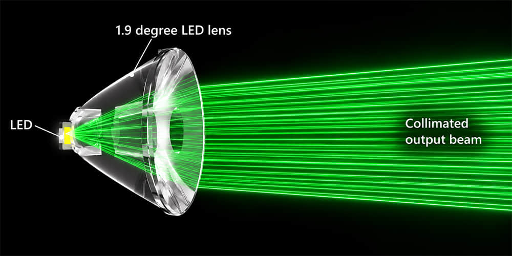
A light collimator is an optical component or system that reduces the angular spread of light rays to create a narrower, more directional beam. In LED lighting, an LED collimator lens collects the wide emission from an LED and redirects it into a controlled beam for long-distance, precision or high-intensity illumination.
Collimation is not the same as simple focusing. A focused optical system brings light toward a defined focal point; a collimator aims to reduce divergence so the output rays are approximately parallel over the useful beam. Because a real LED has a finite light-emitting surface, a compact LED optic cannot produce perfectly parallel light. In practice, the objective is a low-divergence beam with a controlled nominal angle such as 1.9°, 3°, 5° or 9°.
This guide explains how a light collimating lens works, why LED size affects collimation, how beam angle changes the projected spot, and what should be checked before selecting an optic for a narrow-beam lighting project.
What Is an LED Light Collimator?
An LED emits light across a broad range of angles. Without an optic, much of that output spreads outward and is unsuitable for applications that need a concentrated beam over distance.
An LED collimator is designed to collect a substantial portion of this wide emission and redirect it into a smaller angular range. The result can be used for long-throw spotlights, surgical lighting, dental lights, stage effects, stadium fixtures, signalling and focused architectural lighting.
In lighting terminology, “collimator” may describe the complete optical arrangement rather than one material or component type. A collimator can use a lens, reflector, TIR optic or a combination of optical surfaces. An LED lens becomes a collimator lens when its geometry is designed primarily to reduce beam divergence.
How Does an LED Collimator Lens Work?
Many compact LED collimators use several optical regions that work together to control light from both the central and outer portions of the LED emission.
Entrance Surface
The surface nearest the LED receives rays from the light-emitting surface. Its shape and distance from the LED affect how efficiently the optic captures light and how sensitive the final beam is to LED position.
Central Refractive Zone
Rays close to the optical axis are mainly redirected through refraction. This central region contributes to the direction and shape of the forward beam.
TIR Sidewall
Rays emitted at wider angles can strike a shaped sidewall inside the optic. When the conditions for total internal reflection are met, those rays are reflected internally and redirected toward the output direction. This allows a compact TIR collimator lens to collect light that would otherwise leave at wide angles.
Exit Surface
The final optical surface completes beam shaping. Its geometry affects divergence, beam smoothness, center intensity and the appearance of the beam edge.
The relationship between these surfaces is why two lenses with a similar diameter can produce very different narrow-beam performance. It also explains why changing the LED, holder height or lens position can noticeably alter the final beam.
For a more detailed explanation of TIR structures, see our guide to TIR lenses and LED beam control.
Collimated Light vs Focused Light
| Feature | Collimated Beam | Focused Beam |
|---|---|---|
| Primary objective | Reduce divergence and maintain a narrow directional beam | Bring light toward a defined focal point or working distance |
| Ray behaviour | Approximately parallel within the useful output beam | Converges toward a focus, then diverges after it |
| Key specification | Divergence or beam angle | Focal length and working distance |
| Typical applications | Long-distance lighting, signalling, spotlights and precision illumination | Imaging, projection, inspection and optical instruments |
A narrow beam is not automatically a collimated beam. A 10° optic may be appropriate for a spotlight, while a 1.9° optic is designed for much lower divergence and a more concentrated long-distance output.
Can an LED Be Perfectly Collimated?
In most practical LED lighting systems, no. A real LED is an extended source rather than an ideal point source. Its light-emitting surface has physical width, height and angular output characteristics, so rays enter the optic from different positions and directions.
The larger the LED light-emitting surface, the more difficult it becomes for a compact optic to produce an extremely narrow beam. Lens diameter, lens height, source-to-lens distance, LED alignment and the optical system’s available collection angle all influence the achievable divergence.
This means a nominal 1.9° beam belongs to a specific tested combination of LED, optic, holder and measurement conditions. It does not mean that the same lens will produce a 1.9° beam with every compatible LED package.
For narrow-beam development, check the LED model and light-emitting-surface dimensions before choosing an optic. Replacing a small 3535 LED with a larger source can widen the beam, reduce peak intensity or create a less-defined beam edge.
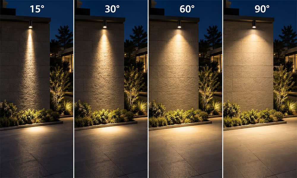
How Beam Angle Affects Projected Spot Size
For a first geometric estimate, projected spot diameter can be calculated as:
Spot Diameter ≈ 2 × Distance × tan(Beam Angle ÷ 2)
When a beam angle is specified at FWHM, the result estimates the distance between the two points where luminous intensity falls to 50% of the peak value. It is not a hard edge of illumination, a zero-light boundary or a guarantee of usable target coverage.
| Nominal Beam Angle | Estimated FWHM Diameter at 5 m | Estimated FWHM Diameter at 10 m | Estimated FWHM Diameter at 20 m |
|---|---|---|---|
| 1.9° | Approx. 0.17 m | Approx. 0.33 m | Approx. 0.66 m |
| 5° | Approx. 0.44 m | Approx. 0.87 m | Approx. 1.75 m |
| 10° | Approx. 0.87 m | Approx. 1.75 m | Approx. 3.50 m |
Actual spot appearance can differ from this calculation because of LED source size, the intensity definition used for beam angle, optic tolerances, LED-to-lens alignment, optical surface quality and the beam’s edge distribution. Use measured polar curves, beam images or IES data when a target size or intensity requirement is critical.
TIR Collimator vs Reflector
| Factor | TIR Collimator Lens | Reflector |
|---|---|---|
| Primary light-control method | Refraction plus total internal reflection inside a transparent optic | Reflection from a shaped cavity or coated surface |
| Mechanical profile | Often compact and close-coupled to the LED | May require greater depth for tight beam control |
| Source format | Often suitable for small LEDs and controlled LED modules | Often practical for COB sources and larger luminous surfaces |
| Alignment sensitivity | Narrow-beam designs can be highly sensitive to LED centering and height | Source depth and centering remain important, especially with tighter distributions |
| Common applications | Precision spots, surgical lighting, stage lighting and compact directional modules | Downlights, track lights, COB spotlights and deeper fixture structures |
The right solution depends on the LED source, required beam, available fixture depth, target distance and mechanical tolerances. A TIR collimator is not automatically better than a reflector; it is a different optical approach with different constraints.
Examples of Narrow-Beam Asahi Optics
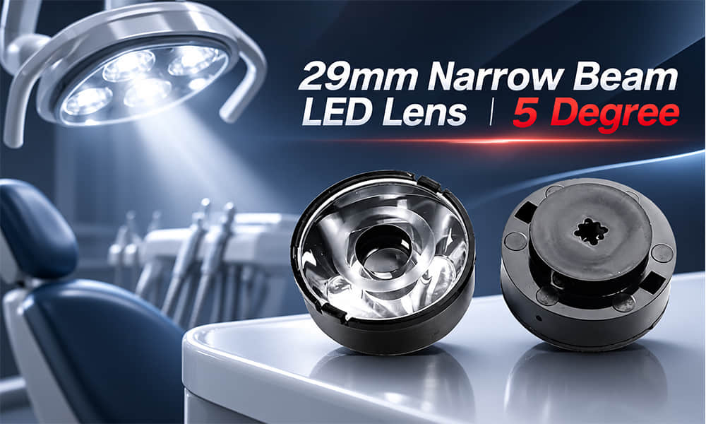
The following published products show how collimating and narrow-beam optics vary in size, LED compatibility and application. Their nominal beam angles should be evaluated with the specified LED and complete fixture structure.
| Model | Nominal Beam | Compatible LED Type | Published Size | Typical Application |
|---|---|---|---|---|
| AJYS56D38H1.9G | 1.9° | XPE-2, XPG-2, XPG-3, XML, P8 | Ø55.4 mm × 38.5 mm | Long-distance and high-intensity illumination |
| AYS29DH17-5G | 5° | 3535 / 5050 LEDs | Ø29 mm × 16.85 mm | Dental lighting, torch lights and focused technical lighting |
| AJSP342D288H9G | 9° | 3737, 3535, XP-E and XP-G LEDs | Ø342.6 mm × 288.1 mm | Stadium lighting |
The comparison also illustrates an important engineering principle: an extremely narrow beam may require a larger or deeper optic, depending on LED source size, collection angle and target requirement.
How to Select an LED Collimator Lens
Do not select a collimating lens only by its nominal beam angle. The following information is needed to screen an existing optic properly:
- LED manufacturer and full model: confirms package geometry and intended source conditions.
- Light-emitting-surface size: strongly affects achievable beam divergence.
- Required beam angle: defines the starting optical range, such as 1.9°, 3°, 5° or 9°.
- Working distance and target spot size: connects beam divergence to the real application.
- Target illuminance or intensity requirement: determines whether the available output is sufficient at distance.
- Maximum lens diameter and height: confirms whether the optic can fit inside the fixture.
- PCB and holder structure: determines LED position, alignment and assembly repeatability.
- Material and temperature requirements: help determine whether PMMA, PC, silicone or another optical material is appropriate.
For circular narrow, medium and wide optical formats, browse our single LED lens range. If the required beam, LED arrangement or mechanical space is not covered by an existing product, the project should be evaluated as a complete optical system.
Common LED Collimator Design Problems
| Observed Issue | Possible Cause | Recommended Check |
|---|---|---|
| Beam is wider than expected | Larger LED emitting surface, wrong LED position or lens-height variation | Verify the actual LED model and source-to-lens distance against the intended optical condition. |
| Beam center is shifted | LED solder offset, holder misalignment or lens tilt | Check LED position against PCB reference points and inspect lens seating. |
| Strong center hotspot | Optic too narrow for the target, insufficient beam overlap or source mismatch | Review the polar curve and target-plane illuminance map before changing the lens. |
| Dark ring or uneven edge | Source mismatch, optical-surface geometry or incomplete beam overlap | Compare beam images with the intended LED and test the optic under controlled assembly conditions. |
| Yellow edge or colour separation | LED angular colour variation, phosphor structure or insufficient colour mixing | Compare another LED sample and inspect whether the colour pattern changes with LED orientation. |
| Simulation does not match measurement | Differences in LED ray data, material properties, molding tolerance or fixture reflections | Measure the assembled module and confirm all simulation inputs match the actual configuration. |
Applications for Light Collimators
Light collimators are used where a fixture must send light accurately toward a relatively small target or maintain useful intensity over a long working distance. Typical applications include:
- Surgical and dental lighting
- Stadium and high-mast lighting
- Stage and special-effect lighting
- Searchlights and signalling equipment
- Machine vision and long-distance inspection
- Architectural accent and façade lighting
For applications requiring a focused narrow beam with controlled source matching, review our surgical lighting optics and stadium lighting lens options.
Request an LED Collimator Lens Recommendation
To evaluate an existing LED collimator lens, send your LED model, LED quantity, PCB layout, lens-space limitations, target distance, required spot size and intended application. If available, include a fixture cross-section, polar curve, IES file or target illuminance requirement.
Asahi can help screen compatible LED lenses and provide available drawings, beam information and photometric files for evaluation. This gives your team a practical starting point before prototype testing or a new optical-development decision.