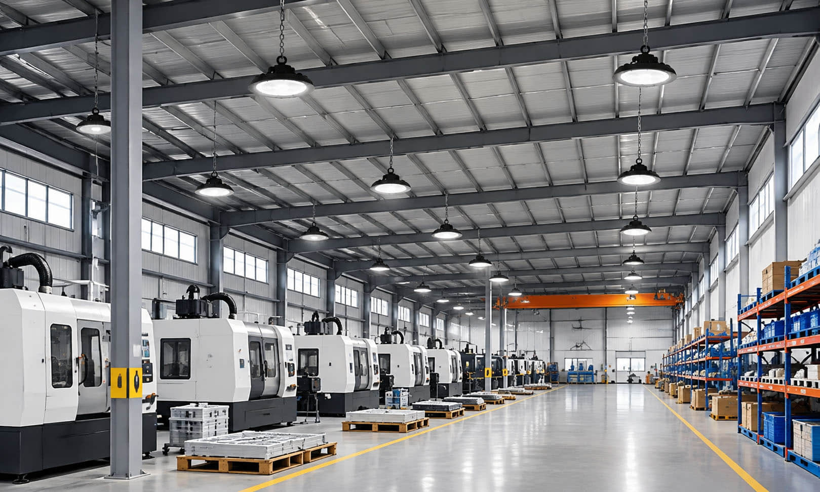
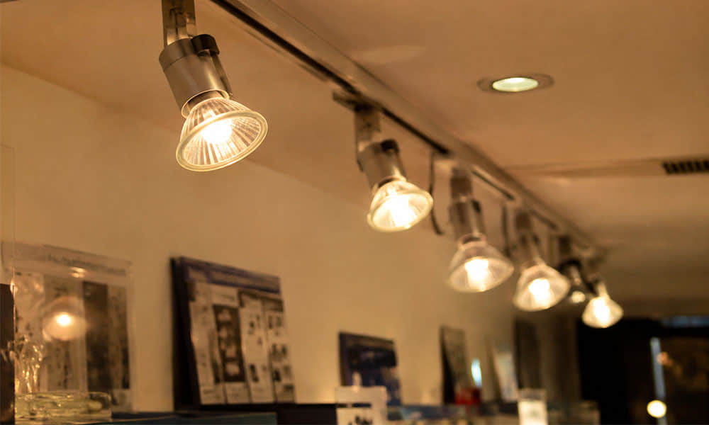
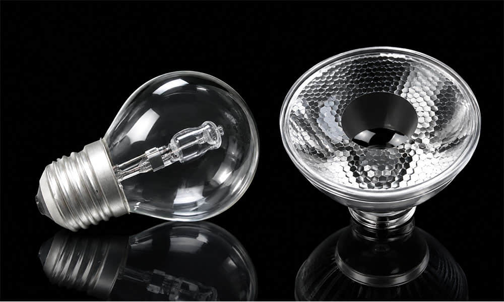
A TIR lens is an LED optic that uses refraction and total internal reflection to collect light from an LED package and redirect it into a controlled beam. It is widely used in spotlights, wall washers, track lights, downlights, architectural luminaires and compact directional lighting modules.
For an engineer, the important question is not whether a lens is labelled “10°,” “30°” or “60°.” The real question is whether that optic can create the required distribution when used with the actual LED, PCB, holder, housing, cover and mounting condition of the finished luminaire.
A TIR optic can provide compact and effective beam control, but it cannot remove the physical limits created by a finite LED emitting surface. The LED source size, lens diameter, lens height and assembly accuracy all affect the final photometric result.
What Is a TIR Lens?
TIR stands for total internal reflection. A TIR lens is normally a molded transparent optic with a central refractive zone, shaped internal sidewalls and an exit surface. Rays entering the central zone are mainly redirected by refraction, while wider-angle rays can be redirected by internal reflection at the sidewall.
Unlike a simple convex lens, a TIR optic is designed to collect a large angular portion of LED output in a compact form. Unlike a reflector, the optical surface is part of a transparent molded part rather than a coated reflective cavity.
How Does a TIR Lens Work?
Total internal reflection occurs only when light travels from a medium with a higher refractive index to one with a lower refractive index, such as from PMMA or PC into air. If the incident angle, measured relative to the surface normal, is greater than the critical angle, the ray reflects internally instead of refracting out of the material.
The critical-angle relationship can be written as:
θc = arcsin(n2 / n1)
Here, n1 is the refractive index of the lens material and n2 is the refractive index of the surrounding medium. As an engineering reference, if a PMMA lens is approximated with a refractive index of 1.49 and the surrounding medium is air with an index close to 1.00, the calculated critical angle is approximately 42.2°. Actual values vary with material grade, wavelength and temperature, so this number should not be treated as a product specification.
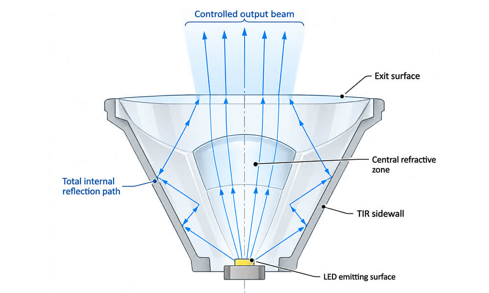
The lens surface closest to the LED does not control every ray in the same way. Some rays are refracted through the central optical zone; others strike the sidewall at an angle that supports total internal reflection. The exit surface then contributes to the resulting intensity distribution. The precise balance between these paths is what separates a narrow spot optic from a medium, wide or oval-beam optic.
For a deeper reference, Ansys explains the TIR condition as a high-index-to-low-index transition where the ray angle relative to the surface normal is too large to satisfy the refraction condition.
Why a Larger LED Makes a Narrow Beam More Difficult
A point source can theoretically be collimated very effectively when it is positioned correctly in an optical system. A real LED is not a point source: its emitting area has width, height and angular distribution. Each point across that emitting surface enters the optic from a slightly different location and direction, so the output cannot become perfectly parallel.
This limit is related to étendue, also called optical extent. In practical lighting terms, a larger source requires either a larger optic or a wider final beam. A small lens cannot collect all of the output from a larger LED and turn it into an extremely narrow beam without trade-offs in beam quality, collection angle or usable flux.
One published illumination-design example uses a 0.3 mm × 0.3 mm source and a 100 mm² output area. Under idealized assumptions, it calculates a best possible divergence of approximately ±1.70°. The purpose of the example is not to specify a commercial lens; it demonstrates the physical trade-off between source size, optical size and beam collimation. See the Ansys illumination-design reference for the underlying étendue discussion.
This is why a 30° optic tested with one small 3535 LED may create a noticeably broader or less-defined beam when installed over a larger COB or a different LED package. The nominal beam angle belongs to a tested optical combination, not to the lens shape alone.
TIR Lens vs Reflector: Which Is Better for Your Fixture?
TIR lenses and reflectors both shape LED light, but they offer different trade-offs. The best choice depends on the source size, required beam shape, fixture depth, visual appearance and production structure.

| Decision Factor | TIR Lens | Reflector |
|---|---|---|
| Light-control principle | Refraction plus total internal reflection inside a transparent optic | Reflection from a shaped cavity, commonly with a reflective coating or surface treatment |
| Best source format | Often well suited to small LEDs and compact LED modules where source position can be controlled accurately | Often practical for larger COB sources and luminaires with more available optical depth |
| Mechanical profile | Can provide a compact optical assembly close to the LED | May require a deeper cavity to achieve comparable directional control |
| Beam edge and beam shaping | Can produce defined narrow, medium, wide or elliptical distributions depending on the optical design | Can create useful directional beams, but output shape depends strongly on reflector depth, aperture and source position |
| Hotspot and source imaging | Requires careful matching to the LED emitting surface and lens position | Reflector shape, source depth and aperture treatment influence center intensity and visible source appearance |
| Color mixing | Polished surfaces with limited color-mixing features may preserve angular color differences from the LED | Texture, coating and cavity geometry may help mix light, but can also create losses or non-uniformity |
| Stray-light control | Depends on the optic, holder, lens edge and surrounding housing surfaces | Depends on aperture shielding, reflector edge geometry and reflective-surface condition |
| Long-term consideration | No reflective coating is required for the TIR sidewall itself, but optical material and surface quality remain important | Reflective coatings and finishes should be evaluated for the operating environment and long-term appearance |
| Assembly tolerance | Narrow-beam products can be sensitive to LED centering, lens height and tilt | Source position inside the reflector remains important, especially for tighter distributions |
Choose a TIR optic when the project requires compact beam control and the LED-to-lens position can be controlled reliably. Consider a reflector when the source is larger, the luminaire has more depth, a specific visual aperture is required, or the project benefits from a reflective cavity rather than a close-coupled lens.
Understanding TIR Lens Beam Angles
Beam angle is commonly specified at the points where luminous intensity falls to 50% of the peak value, often called the full width at half maximum (FWHM). However, this definition is not identical across every supplier or test setup. Always check the stated test condition, LED model and photometric definition before comparing beam angles from different products.
Narrow Beam TIR Lenses
Narrow-beam optics are typically used for accent lighting, wall washing, display lighting and long-throw directional illumination. They can deliver a concentrated beam, but also make LED centering and aiming more critical.
As a documented example, Asahi model ALS21D10G is specified as a 10° optic for 3535 LEDs. The published product information lists a diameter of Ø21.58 mm, a height of 11.4 mm, PMMA material and light transmission above 90%. Compatible LED families listed on the page include Cree XP-E / XP-G series, OSRAM OSLON SSL80, Lumileds LUXEON HL4Z and Nichia NVSW219GL.
These are actual product parameters, not generic beam-angle claims. The final peak intensity, FWHM and beam symmetry still depend on which compatible LED is selected, its drive current, the mounting position and the completed luminaire structure.
Medium and Wide Beam TIR Lenses
Medium beams are often selected for track lights, retail displays and general accent lighting where a balance between coverage and directional emphasis is needed. Wide beams are more suitable for shorter mounting distances and larger target areas, but fixture spacing and overlap remain important for uniform illumination.
A wider beam should not automatically be interpreted as better uniformity. A wide optic may reduce center intensity, while multiple narrow or medium optics may create better target control in some layouts. The correct choice depends on the target dimensions and fixture arrangement.
Oval and Asymmetric Optical Distributions
Some projects require rectangular or directional coverage rather than a circular beam. Oval optics can help cover elongated targets, while asymmetric distributions are designed to direct light toward one side of the fixture position. For road and area lighting, use dedicated street and area lighting optics rather than attempting to apply a standard circular TIR beam to an asymmetric roadway task.
What Should Be Tested Before Approving a TIR Lens?
A useful optical evaluation compares alternatives under controlled conditions. The LED model, drive current, PCB, thermal condition, lens holder and measurement method should remain unchanged unless one variable is intentionally being studied.
| Test Condition | What to Measure | What the Result Helps Identify |
|---|---|---|
| Baseline: intended LED, normal centered assembly | FWHM, peak candela, total luminous flux, polar curve and beam-center position | Reference performance of the intended optical system |
| Alternative LED with a larger emitting surface | FWHM, center intensity, color pattern and spill light | Whether source size changes the beam beyond the project requirement |
| Controlled horizontal lens or LED offset | Beam-center shift, left/right intensity balance and polar-curve symmetry | Sensitivity to PCB placement, solder position and holder centering |
| Controlled lens-height variation | Peak intensity, beam angle and hotspot appearance | Sensitivity to holder height and mechanical stack-up tolerance |
| Lens tilt or uneven seating | Beam aiming, asymmetry and cutoff appearance | Whether the installation reference surfaces are adequate |
| Fixture test with and without cover or nearby reflective parts | Stray light, side lobes, color appearance and distribution changes | How the final luminaire structure affects the optic |
There is no universal rule that a 0.2 mm offset or a 0.3 mm height change will produce a fixed percentage loss. The effect depends on the specific LED, lens geometry, beam angle and holder design. Publishing a number without the complete test condition would look precise but would not be technically transferable.
For this reason, a proper photometric report should identify the LED model, drive current, sample structure, measurement method, ambient condition and tested optic. When the requirement is critical, evaluate the assembled module with a goniophotometer and review the resulting polar curve and IES data.
TIR Lens Troubleshooting: Symptoms, Checks and Practical Actions
| Observed Symptom | Likely Causes | How to Verify | Typical Next Action |
|---|---|---|---|
| Yellow edge or color ring | LED angular color variation, phosphor structure, source-to-lens mismatch, lens dispersion or insufficient color-mixing features | Rotate the lens while keeping the LED fixed; then rotate or replace the LED while keeping the lens orientation fixed. Compare the color pattern before and after each change. | If the pattern rotates with the LED, investigate the LED’s angular color behavior. If it stays with the lens, evaluate optic geometry, material and color-mixing features. |
| Beam center is shifted left, right or upward | LED solder-position error, holder offset, lens tilt or uneven lens seating | Measure beam center on a target plane. Check LED position relative to PCB fiducials, then inspect holder contact points and lens seating. | Correct the mechanical locating reference before changing the optic. A lens change may hide the symptom without solving the assembly cause. |
| Excessive center hotspot | Beam too narrow for the installation distance, insufficient overlap, source mismatch or output distribution not suited to the target | Review the polar curve and target-plane illuminance map. Compare center intensity with the intensity at the intended beam edge. | Evaluate a wider or different distribution, adjust mounting distance or redesign fixture spacing. Do not rely on nominal beam angle alone. |
| Unexpected side spill or stray light | Lens edge leakage, reflective holder surfaces, cover interaction, housing reflections or incorrect LED height | Test the module without the cover; then temporarily mask nearby holder or housing surfaces with matte black material and compare the distribution. | Identify the component responsible before changing the primary optic. A holder, cover or reflective cavity may be the real source of spill light. |
| Beam becomes wider than the nominal specification | Larger LED emitting area, different package geometry, lens-height change or incorrect LED position | Compare the intended LED with the actual source and verify the mechanical distance from LED emitting surface to lens reference plane. | Use the LED package specified for the optic where possible, or re-evaluate the lens with the actual source and fixture structure. |
Why Simulation and Measured Results Can Differ
Optical simulation is valuable for comparing concepts, but it is not a substitute for module testing. A ray file may not fully represent the LED batch used in production. The actual emitting area, phosphor pattern, package tolerances, drive current and thermal state can all differ from the design assumption.
Measured results can also change because of lens shrinkage after molding, optical-surface quality, material variation, lens-holder tolerances, protective covers and reflective surfaces inside the housing. These factors explain why a simulation may predict the general distribution correctly while the measured beam shows a shifted hotspot, wider FWHM or additional spill light.
For projects requiring lighting calculations, a measured IES photometric file provides a more complete description of the fixture’s actual distribution than a beam-angle label alone.
When a TIR Lens Is Not the Best Choice
A TIR lens is not automatically the best optical solution. If the LED source is large, the fixture requires an extremely broad diffuse field, or the mechanical design cannot maintain accurate LED-to-lens positioning, another optical approach may be more appropriate.
Reflectors can be effective for larger COB assemblies or fixtures with sufficient depth. Diffusers and linear optics may be better suited to continuous, soft illumination. For roadway applications, specialized asymmetric optics are generally required because the target is not circular and the light must be distributed across a defined road geometry.
The most reliable decision is based on the LED source, target shape, installation height, required illuminance, uniformity target, fixture structure and verified photometric output.
Request an Existing TIR Lens Recommendation
To evaluate an existing TIR lens efficiently, provide the LED model and datasheet, LED quantity, PCB layout, target size, mounting height or working distance, required distribution and available mechanical space. If you have a holder drawing, IES file, polar curve, lux target or fixture cross-section, include those as well.
Asahi can screen compatible existing optics and provide available drawings, beam information and photometric files for evaluation. This gives the project team a practical starting point before committing to a prototype or fixture-level test.