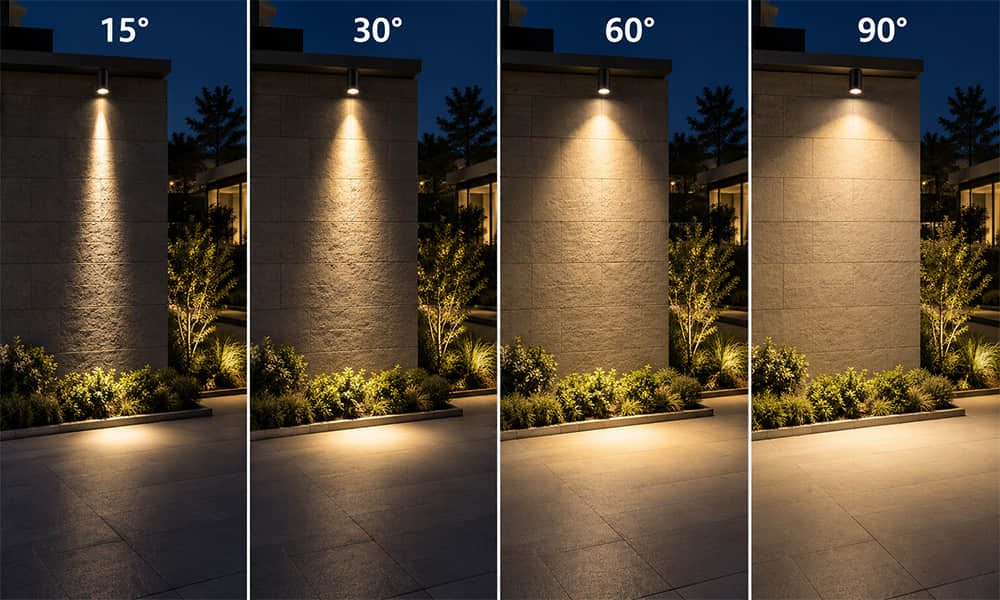
For many years, Asahi Optics has been recognized primarily as a specialized designer and manufacturer of LED optics, producing high-performance street lighting lenses, stadium high-mast arrays, and complex optical systems for commercial applications.
However, evaluating our manufacturing capabilities solely through the lens of optical design overlooks a fundamental technical reality: the core competence required to manufacture a flawless optical lens is identical to the competence required for high-precision vehicle plastic components.
The physical laws governing the production of a distortion-free optical lens are among the most unforgiving in the plastics industry. A variance of mere microns in tool geometry, a minor fluctuation in barrel temperature, or a split-second drop in packing pressure will cause volumetric shrinkage, internal stress fractures, and optical wavefront deviations that render the lens unusable.
Over decades of refining our optical production, we have established an engineering ecosystem centered on micro-tolerance mold design, rigid process parameter control, and a zero-defect quality management framework.
Today, we are actively leveraging this advanced injection molding capability to expand our manufacturing services beyond LED lenses. Asahi Optics provides comprehensive custom plastic injection molding for high-stress vehicle accessories, micromobility components, and motorcycle helmet precision accessories (including helmet visor brackets, ventilation mechanisms, internal locking components, and exterior structural fairings).
The decision to feature our motorcycle helmet component manufacturing is a calculated one. A motorcycle helmet is a critical piece of personal protective equipment (PPE). Its functional plastic accessories must meet strict engineering parameters that directly parallel the requirements of automotive interior trims, exterior bezels, and lighting housings. These components must display high impact resistance under fluctuating temperatures, absolute dimensional repeatability to maintain airtight and watertight seals, and flawless surface finishes free of sink marks or visible weld lines.
By demonstrating how we apply car-grade engineering and molding disciplines to these complex helmet accessories, this capability article will show you our physical factory setup. We will detail how our capital investments in high-specification GSW injection molding machines, combined with our certified IATF 16949 quality management system, allow us to act as a reliable, single-source manufacturing partner for your structural, functional, and aesthetic plastic projects.
What Are the Precise Injection Molding Challenges for Motorcycle Helmet Accessories?
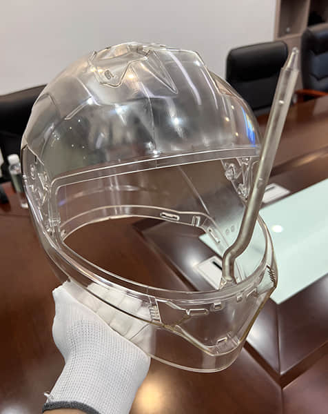
To evaluate why a motorcycle helmet component serves as an effective benchmark for our broader automotive molding capabilities, it is necessary to analyze the physical and cosmetic constraints placed on these parts. As established in our manufacturing boundaries, our production focuses specifically on the intricate, functional structural accessories of the helmet—such as helmet visor brackets, ventilation switch buttons, internal locking components, and aerodynamic spoiler fairings.
These micro-components dictate the performance and reliability of the protective gear. If a visor mechanism binds or fractures under low temperatures, the safety system fails.
1. Managing Non-Uniform Wall Thicknesses
A significant geometric challenge in precision plastic injection molding is the management of non-uniform wall thicknesses. Structural parts like a helmet visor bracket or an automotive mounting clip frequently require thin, flexible outer flanges (1.5 mm1.5 mm to 2.0 mm2.0 mm) that intersect abruptly with thick internal screw bosses or stiffening ribs (4.0 mm4.0 mm to 6.0 mm6.0 mm) designed to withstand mechanical loads.
When molten plastic is injected into a cavity with these characteristics, the thin sections cool and solidify rapidly, while the heavy core of the thick sections remains molten much longer. As this internal molten mass cools, it experiences volumetric thermal contraction.
Without precise processing control, this contraction pulls the outer solidified skin inward, creating a visible surface depression known as a sink mark, or creating an internal structural void that compromises the mechanical strength of the mounting point. Leveraging our experience with thick-walled optical lenses, we mitigate these shrinkage variations through precise, multi-stage pressure profiling.
2. Achieving Surface Consistency and Eradicating Weld Lines
The majority of functional helmet accessories are mounted directly on the class-A aesthetic exterior surfaces of the vehicle or safety gear, making them subject to immediate quality scrutiny. Under standard manufacturing conditions, a mold cavity with complex core pins and multi-point gates will generate weld lines—the boundary lines formed where two or more separate streams of molten plastic meet inside the tool.
For outdoor mobility products, a visible weld line represents both a cosmetic failure and a structural fault line. Under mechanical vibration, cold-weather impact, or sudden shock loading, a weld line acts as a stress concentrator where the component can prematurely fracture. Our facility ensures structural consistency by optimizing gate positioning to force polymer chains to entangle fully across every junction, rendering the final component completely homogeneous.
3. Material Processing Requirements: PC, ABS, and PC/ABS Blends
Surviving outdoor mobility environments requires raw materials that can handle continuous environmental stress. We process high-grade engineering polymers tailored to specific functional profiles:
-
Polycarbonate (PC) : Utilized for transparent components and high-impact visor linkages due to its high impact resistance and mechanical toughness across a broad temperature scale (−20∘C−20∘C to 120∘C120∘C).
-
Acrylonitrile Butadiene Styrene (ABS) : Selected for internal sliders and vent buttons where structural rigidity, surface hardness, and dimensional stability are required.
-
PC/ABS Alloys: Used for external ventilation housings. This material blends the high impact strength and UV weatherability of PC with the processing ease and structural stiffness of ABS.
Processing these resins requires strict thermal management. Amorphous polymers like PC are highly sensitive to shear stress and moisture-induced degradation during the melting phase.
Our Injection Molding Machinery: GSW Machine Matrix, Tonnage Distribution, and Automation
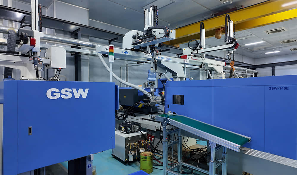
The reliability of a custom plastic manufacturing partner depends heavily on the capability, precision, and scaling of its production machinery. To translate strict automotive and mobility engineering requirements into highly repeatable physical components, Asahi Optics has established a fully integrated, automated injection molding shop. Our facility layout utilizes a strategic matrix of high-precision GSW (Haitian Zhafir) injection molding machines, spanning clamping forces from small-scale precision units to heavy-tonnage infrastructure systems.
1. Tonnage Allocation and Component Specialization
Our machinery infrastructure is grouped by clamping tonnage to ensure that every molded component—regardless of mass or footprint—is processed on a machine optimized for its volumetric displacement and projection area.
-
50-Ton to 160-Ton GSW Units (Micro-to-Small Format) : This line is dedicated to ultra-low-mass components requiring microscopic positional tolerance. Typical outputs include high-precision optical lenses, internal helmet snap-fasteners, locking mechanisms, and specialized automotive electrical clips.
-
200-Ton to 450-Ton GSW Units (Mid-Sized Format) : This tonnage band represents the highest density of workhorses on our factory floor. These machines process components with intermediate surface areas and complex core-pull configurations, such as helmet visor brackets, ventilation housings, vehicle indicator covers, and internal electronic module brackets.
-
650-Ton to 1600-Ton GSW Units (Large Format) : Reserved for large projected surface areas and high-volume multi-cavity tools. These heavy-duty structural machines are used to manufacture oversized mobility enclosures, commercial lighting housings, EV battery structural trays, and aerodynamic exterior vehicle trims.
By distributing production across this structured tonnage spectrum, we maintain appropriate clamping pressures, eliminate flash formation, and prevent structural material degradation caused by excessive residence time in an oversized barrel.
2. Automation and Robotic Handling Integration
Manual part extraction introduces cycle-time variability, which changes the cooling profile of the mold and alters the dimensional consistency of the finished plastic part. To achieve the part-to-part uniformity required by IATF 16949 standards, every GSW machine in our shop is integrated with a dedicated 3-axis servo robotic arm.
The automated sequence follows a strict timeline:
-
The GSW clamping unit opens precisely upon completion of the cooling cycle.
-
The overhead pneumatic or servo-driven robotic arm enters the mold space, engages custom suction or mechanical grippers, and extracts both the part and the runner system.
-
The arm deposits the component onto a synchronized cooling conveyor system while simultaneously managing sprue separation.
This automation locks the cycle time to a variance of less than ±0.1 seconds±0.1 seconds. The elimination of manual extraction protects delicate aesthetic surfaces from human handling damage, maintains an unbroken thermal cycle inside the tool steel, and guarantees steady volume output.
3. Peripheral Auxiliary Systems for Material Integrity
An injection molding machine cannot function in isolation; its output is directly dependent on its surrounding auxiliary support hardware. Our GSW fleet is supported by an interconnected network of closed-loop peripheral systems:
-
Desiccant Honeycomb Dryers: Amorphous engineering plastics like Polycarbonate (PC) absorb atmospheric moisture. If processed wet, the water molecules undergo hydrolysis at melt temperatures, breaking down the polymer chains and reducing impact resistance by up to 50%. Our centralized drying loops ensure that resins entering the GSW injection hoppers maintain a moisture content below 0.02%0.02%.
-
Advanced Mold Temperature Controllers (MTC) : We utilize dual-zone oil and water MTCs to maintain constant, elevated mold face temperatures. For parts like helmet vent sliders or automotive bezels, precise mold temperature regulation controls the crystallization rate of the polymer, ensuring uniform surface gloss and reducing molded-in residual stresses.
-
Industrial Central Chilling Plant: Our molds feature optimized cooling channels supplied by high-flow, temperature-stabilized water loops. Rapid, controlled cooling shortens the overall cycle time while ensuring structural stability across varying production seasons.
The Core Injection Molding Process: From Moldflow Analysis to Parameter Optimization
Machinery and raw materials form the physical baseline of our production floor. However, transforming a digital 3D model into an automotive-grade structural component requires strict, data-driven parameter management at every stage of the manufacturing cycle.
To prevent warping, structural weakness, and surface degradation, Asahi Optics manages its molding cycles through a structured four-stage process loop.
1. Pre-Tooling Validation via Moldflow Simulation
Defect prevention begins before tool steel is cut. For every complex vehicle accessory—such as an asymmetric helmet visor bracket or an internal electronics enclosure—our engineering division executes a comprehensive Moldflow analysis.
This computational fluid dynamics simulation maps the behavior of the specific resin (e.g., Polycarbonate or ABS) as it progresses through the runner and gates into the tool cavity.
Our simulation protocols focus on three critical engineering indicators:
-
Gate Placement Optimization: The simulation identifies the ideal entry point for the molten polymer. Correct positioning ensures balanced volumetric filling and ensures that unavoidable weld lines are driven into non-aesthetic, structurally non-critical zones of the component.
-
Cooling Circuit Analysis: We map thermal dissipation across the entire tool geometry. By analyzing localized heat concentration, we design custom cooling channels that track the contours of the part, reducing differential cooling stresses and shortening the baseline cooling cycle by up to 30%30%.
-
Warpage Prediction: The software calculates potential dimensional deflection caused by fiber orientation or asymmetric contraction. If the predicted deflection exceeds our internal threshold (±0.05 mm±0.05 mm), the part geometry or tool layout is modified prior to manufacturing the physical mold.
2. Multi-Stage Injection Speed and Pressure Profiling
Amorphous engineering polymers are highly sensitive to velocity changes and localized shear heat during injection. Injecting material at a single, uniform speed can cause surface defects such as jetting marks near the gate or burn marks at the far end of the cavity due to trapped air.
To address this, our GSW injection molding machines utilize advanced multi-stage injection profiling. A typical profile for a structural mobility component is divided into specific speed-and-pressure zones:
-
Stage 1 (Slow Start) : The screw advances at a reduced velocity to fill the runner system and pass smoothly through the restricted gate area, preventing localized shear degradation.
-
Stage 2 (Fast Filling) : The velocity increases sharply to fill the primary volume of the cavity quickly, keeping the melt front hot and preventing premature solidification in thin-walled sections.
-
Stage 3 (Slow Finish) : As the cavity reaches approximately 95%95% volumetric capacity, the injection speed drops to prevent pressure spikes, minimizing flash formation and protecting the mechanical venting inserts.
3. Transition Controls and Optimizing Holding Parameters
The transition from the injection phase to the packing phase—known as the V/P (Volume-to-Pressure) switchover point—is critical for part weight consistency and dimensional stability. Our GSW control loops trigger this switchover based on precise screw position metrics down to ±0.01 mm±0.01 mm.
Once the V/P switchover occurs, the machine shifts from controlling flow velocity to managing holding pressure. The primary function of holding pressure is to feed additional molten material into the cavity to compensate for the volumetric shrinkage that occurs as the plastic cools.
For thick-walled vehicle accessories, we apply a step-down holding profile: maintaining high initial pressure to pack out internal bosses and eliminate sink marks, followed by a gradual pressure reduction to prevent excessive molded-in stress near the gate region.
4. Cooling Time Management and Real-Time Monitors
The cooling phase typically accounts for 60%60% to 80%80% of the total injection molding cycle time. A part must remain inside the temperature-controlled tool until its internal temperature falls below its heat deflection threshold, ensuring it is rigid enough to withstand ejection forces without flexing or warping.
Our GSW production units are equipped with real-time digital monitoring loops that track every cycle parameter against a locked master reference curve. If a critical variable—such as peak injection pressure, cushion distance, or total cycle time—shifts by even a minor tolerance, the integrated software triggers an automated alarm.
The robotic handling arm automatically isolates the affected shot onto a segregated quality verification conveyor, ensuring that only fully compliant components enter our post-processing and packaging streams.
Quality Control Under IATF 16949: CMM Measurement and Statistical Process Control (SPC)
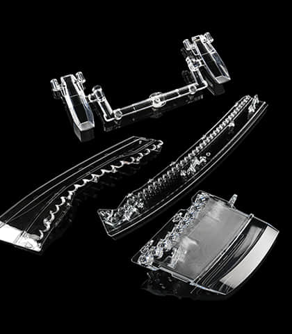
Operating as an approved manufacturer within the automotive, electric vehicle (EV), and advanced mobility supply chains requires more than just high-performance machinery. It demands a highly structured quality management framework capable of preventing defects, reducing variation, and ensuring absolute traceability.
Asahi Optics operates under a fully certified IATF 16949 quality management system, enforcing the same rigorous verification protocols used by international tier-1 automotive suppliers for all our precision plastic components.
1. Metrology Infrastructure: Precision CMM and Optical Measurement Systems
Dimensional compliance cannot be assessed with basic manual tools when manufacturing complex geometries like a multi-link helmet visor bracket, an aerodynamic rear spoiler, or an automotive lighting bezel. Our quality assurance laboratory is equipped with advanced metrology hardware to verify tolerances down to the micron scale:
-
Coordinate Measuring Machines (CMM) : Our automated CMM systems utilize ultra-sensitive touch-trigger and scanning probes to map complex 3D surface profiles against the original master CAD file. This allows our technicians to verify true geometric dimensioning and tolerancing (GD&T) metrics, including sphericity, coaxiality, and precise hole positions on structural mountings.
-
2.5D Optical Video Measuring Systems: For rapid, non-contact evaluation of small plastic parts, fasteners, and internal locking clips, we deploy high-resolution optical measuring systems. These instruments utilize edge-detection algorithms to measure planar dimensions, radii, and angles within seconds, minimizing operator error.
-
Environmental Conditioning and Thermal Stability Testing: Vehicles and personal protective equipment operate across extreme environments. Our lab houses programmable temperature and humidity chambers alongside mechanical tensile testers. We subject sample extractions to continuous thermal cycling and mechanical pull tests to ensure that material assemblies do not experience premature embrittlement, warpage, or stress fractures in the field.
2. Statistical Process Control (SPC) and Real-Time Deviation Monitoring
Under the IATF 16949 framework, quality control shifts from reactive post-production inspection to proactive process monitoring. We implement Statistical Process Control (SPC) across our GSW production loops to detect and correct manufacturing anomalies before a component drifts outside engineering tolerances.
Our SPC workflow tracks key quality indicators through data-driven tracking metrics:
-
Critical Dimension Sampling: At designated production intervals, robotic handling systems route specific parts to inline metrology stations. Critical dimensions—such as the outer diameter of a retention pin or the width of a sealing track—are measured and automatically logged into our centralized SPC tracking software.
-
Capability Index Analysis (CpCp and CpkCpk) : Our software calculates real-time process capability values. We maintain a baseline target of Cpk≥1.67Cpk≥1.67 for critical automotive and mobility components. A high CpkCpk value indicates that the injection molding process is highly centered and well within the allowed tolerance band.
-
Control Chart Mapping: The software generates live control charts tracking dimensional trends. If a trend reveals a gradual shift toward the upper or lower control limit—even if the part remains within the absolute print tolerance—the SPC system flags a potential process drift. Maintenance technicians immediately investigate root causes, such as tool wear, thermal fluctuations, or batch-to-batch resin viscosity changes, ensuring the process is corrected before defects occur.
3. Comprehensive Traceability and Three-Tier Inspection Protocols
To comply with international automotive liability and safety audits, Asahi Optics enforces complete component traceability. Every batch of raw engineering resin is logged upon entry with its respective material certificate, drying log, and assigned master batch code. This code links directly to the specific GSW machine number, mold cavity ID, operator shift log, and real-time SPC parameter file recorded during its manufacture.
Our daily operations follow a strict Three-Tier Inspection Protocol:
-
First-Article Inspection (FAI) : At the beginning of every production run or shift change, the first parts molded are subjected to a full dimensional CMM scan and cosmetic evaluation. Mass production cannot resume until the FAI report receives formal engineering sign-off.
-
In-Process Patrol Inspection: Quality inspectors conduct standardized hourly floor audits at every active GSW molding station, executing visual checks and critical-dimension gauging to ensure process stability.
-
End-of-Run Final Audit: Before any batch is released to the logistics warehouse, sample packages undergo final visual inspections under specialized high-lux lighting hoods to verify the complete absence of flash, sink marks, silver streaks, or cosmetic weld lines.
Beyond Lenses and Helmets: Our Extended Components List, LED Processing Capabilities, and Technical FAQs
The integrated combination of high-specification GSW injection molding machinery, data-driven process controls, and strict IATF 16949 quality frameworks allows Asahi Optics to manufacture a broad range of products beyond LED lenses and motorcycle helmet accessories.
We serve as a single-source manufacturing and LED-processing partner for diverse global industries, delivering components ready for direct assembly line integration.
1. Extended Component Manufacturing Capabilities
Our current production infrastructure is configured to process a wide variety of engineering resins—including PC, PMMA—across several key market sectors:
-
Automotive & Electric Vehicle (EV) Systems: Beyond specialized headlight and signaling optics, we mold structural rear light housings, internal reflective bezels, high-retention dashboard trim clips, instrument cluster covers, EV battery module trays, and impact-resistant charging port lids.
-
Micromobility & Electric Scooters: Functional components including handlebar throttle assemblies, digital display fairings, protective battery compartment enclosures, and structural mudguards.
-
Industrial & Electrical Infrastructure: High-durability sensor housings, terminal block enclosures, heavy-duty electrical switches, and network connector blocks requiring flame-retardant (UL94 V-0) and glass-filled performance characteristics.
2. Comprehensive LED and Post-Molding Processing
To reduce supply chain complexity and lower handling costs for our clients, our facility provides fully integrated post-molding finishing operations:
-
Automated Ultrasonic Plastic Welding: Used to bond multi-part molded assemblies securely without using adhesive chemicals, ensuring airtight and watertight seals for environmental sensor enclosures and vehicle light bodies.
-
Precision Screen and Pad Printing: High-resolution, wear-resistant printing of logos, safety warnings, and functional symbols directly onto aesthetic exterior plastic surfaces.
-
Laser Marking and Engraving: Permanent, automated etching of serialized alphanumeric tracking codes, QR tracking identifiers, and corporate branding marks directly onto structural components.
-
Surface Coating and Metallic Metallization: Specialized coordination lines for anti-scratch hard coatings, UV-protective painting, and vacuum metallization for high-reflectivity automotive optical bezels.
Conclusion: Partner with Asahi Optics for Your Next Precision Molding Project
The precision required to mold high-performance LED optics establishes the baseline for our broader manufacturing operations. By partnering with Asahi Optics for your custom plastic components, you gain access to an asset-heavy infrastructure anchored by precision GSW machinery, backed by data-driven Moldflow parameters, and governed by verified IATF 16949 automotive quality standards.
We eliminate the friction of managing fragmented vendors by providing design-for-manufacturing (DFM) support, precise tool construction, automated mass production, and advanced post-molding finishing under a single unified quality loop. Contact our engineering desk today with your 3D CAD step files or physical prototypes to receive an optimized engineering feasibility review and a competitive manufacturing quotation.
FAQ
Q: What is the specific clamping tonnage range of your GSW injection molding machinery?
A: Our factory floor operates an integrated matrix of high-precision GSW (Haitian Zhafir) machines spanning clamping forces from 50 tons to 1600 tons, optimizing production for micro-precision connectors up to large-scale vehicle body trim panels.
Q: Do your engineering teams provide Moldflow simulation reports prior to mold tooling fabrication?
A: Yes. Under our IATF 16949 engineering workflow, a full Moldflow simulation analysis is executed and reviewed with the client before tool steel is cut. This report covers gate localization, volumetric filling balanced inputs, cooling optimization, and warpage predictions.
Q: Can your facility accommodate small-batch prototype runs, or do you only handle high-volume mass production?
A: While our automated GSW production floor is optimized for high-volume serial production, we maintain a dedicated prototyping cell. We support pilot production and testing validation runs (typically starting from 1,000 pieces) to support the engineering validation testing (EVT) and design validation testing (DVT) phases of your project.
Q: What is the standard engineering lead time for a custom injection mold and first-article sample delivery?
A: For standard mid-sized components (such as functional helmet accessories or internal automotive brackets), structural tool design and mold fabrication typically require 2 to 3 weeks. Following initial tool sampling (T1), verified first-article inspection samples along with full CMM metrology data sheets are delivered within 7 to 10 days.