Asahi Optical Testing Equipment
Preparation
Mold Installation
Initial Injection
Process Optimization
Evaluation and Summary

Preparation Work

This phase is crucial as the foundation for safety and success. It involves completing mold verification, equipment preparation, and material readiness.

Mold Verification and Preheating

Ensure the mold is in good condition and properly preheated.

  • Verify the mold model and cavity count match the production order
  • Confirm smooth operation of ejector pins, sliders, cooling channels, and ensure no foreign objects
  • Pre-heat high-gloss molds or those using high-temperature plastics with a mold preheater in advance

Injection Molding Machine Preparation

Select appropriate equipment and ensure cleanliness.

  • Choose an injection molding machine with adequate tonnage based on mold projected area and injection pressure
  • Thoroughly clean the moving platen, fixed platen, tie bars, and nozzle
  • Prepare the correct plastic raw materials and set drying temperature and time

Auxiliary Tool Preparation

Prepare all necessary tools and equipment.

  • Lifting equipment (overhead crane/forklift)
  • Fastening materials such as bolts, clamp plates, and spacer blocks
  • Connection components including water pipes, air pipes, and thermocouples
  • Tools (wrenches, copper bars, lint-free cloths, etc.) and product sample containers

Mold Installation

Precisely install the mold and connect all auxiliary systems to ensure safe and stable production.

Hoisting and Positioning

Safely hoist and accurately position the mold.

  • Use an overhead crane to steadily lift the mold, adjusting height and angle
  • Open the injection molding machine in slow mode to ensure sufficient space
  • Align the mold locating ring with the machine's locating hole, and center the sprue bushing with the nozzle

Initial Fixing

Securely fasten the mold to ensure stability.

  • Lightly secure the fixed mold side with bolts and clamp plates
  • Manually or slowly close the mold until the moving platen contacts the moving mold side
  • Finally, secure the moving mold side, ensuring all clamp plates are firmly tightened

Auxiliary System Connection

Connect all necessary auxiliary systems.

  • Connect cooling water channels and check for leaks
  • Connect hydraulic/pneumatic circuits (if equipped with hydraulic core-pulling or pneumatic ejection systems)
  • Connect control systems (signal lines for thermocouples, limit switches, etc.)

Process Setting and Initial Injection

Set preliminary process parameters and conduct the first injection test to observe melt flow behavior.

Setting Preliminary Process Parameters

Input conservative and safe initial parameters.

  • Set temperatures for each barrel zone, nozzle temperature, and mold temperature
  • Configure injection pressure, holding pressure, and injection speed (start with low speed)
  • Set injection stroke, holding time/switchover position, and cooling time

Nozzle Alignment and Mold Adjustment

Precisely adjust equipment and mold coordination.

  • Fine-tune the injection machine to ensure tight contact between nozzle and mold sprue bushing
  • Perform "mold height adjustment" to find the minimum stable clamping force suitable for mold thickness

Initial Test Shot (Short Shot)

Critical step to observe melt flow.

  • Intentionally set insufficient injection volume, using low speed and pressure
  • Observe the melt flow behavior within the cavity
  • Assess gate and venting effectiveness
  • Identify weld lines and venting locations through short-shot products

Process Optimization and Sample Collection

Gradually optimize process parameters, stabilize production, and collect representative samples.

Parameter Optimization

Progressively adjust parameters to achieve optimal results.

  • Filling Phase: Gradually increase injection speed and pressure until the cavity is precisely filled
  • Holding Phase: Introduce holding pressure and time to eliminate sink marks while avoiding flash
  • Other Parameter Optimization: Cooling time, mold temperature, back pressure, etc.

Stable Production and Sampling

Collect representative samples under stable conditions.

  • Allow the injection machine to run continuously in automatic mode for a period
  • Collect samples at predetermined intervals (e.g., every 10th shot, 50th shot)
  • Clearly mark shot numbers for subsequent tracking and analysis

Evaluation and Follow-up Work

Comprehensively evaluate sample quality, prepare a trial report, and establish the foundation for subsequent mass production.

Sample Evaluation

Conduct thorough inspection of sample quality.

  • Full Dimensional Inspection: Measure dimensions using CMM, optical projector, and other tools
  • Visual Inspection: Check for defects such as sink marks, silver streaks, bubbles, and scratches
  • Functional Testing: Perform assembly verification or optical performance testing

Mold Handling

Properly handle the mold to ensure long-term preservation.

  • Material Purging: Empty or clean residual plastic from the barrel
  • Rust Prevention: Spray rust preventive into the cavity
  • Mold Removal: Disconnect all connections and hoist the mold out of the injection machine

Trial Report Preparation

Document key information for future reference.

  • Trial date, personnel, machine number, and mold identification
  • Final process parameter sheet
  • Identified issues (mold problems, product defects)
  • Optimization suggestions and modification plans
  • Sample inspection results

Ensuring Optical Performance Matches Design Specifications

Before formal mass production, we install trial-produced sample lenses on LED luminaire for comprehensive optical testing. This critical step verifies whether the lens optical performance meets design requirements, ensuring the final product achieves the customer's expected illumination outcomes. Optical testing not only validates compliance with technical specifications but, more importantly, guarantees ideal lighting performance in real-world applications.

Optical Testing Process

1
Sample Preparation and Pre-treatment

Randomly select representative samples from trial production batches to ensure statistical significance. Samples must undergo strict cleaning procedures and stabilize under standard environmental conditions for at least 2 hours.

2
Optical Test on Customer's Luminaire

Select matching LED light sources according to customer application requirements, using high-precision positioning fixtures to ensure repeatable installation accuracy within ±0.05mm.

3
Optical Parameter Testing and Data Acquisition

Conduct testing in darkroom environments to eliminate ambient light interference. Test parameters cover key indicators including luminous flux, optical efficiency, light distribution curves, color temperature, and color rendering index.

4
Performance Analysis and Verification

Process test data using professional optical analysis software, generating visual reports such as light distribution curves, iso-illuminance diagrams, and 3D light intensity distribution maps.

Key Testing Parameters

Light Intensity Distribution and Photometric Curve

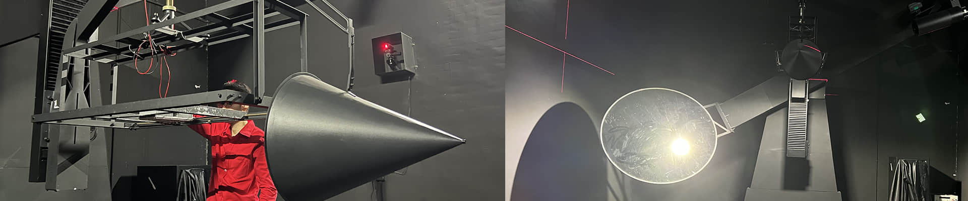
Using a goniophotometer to measure the light intensity values of the lens in various directions, plotting a complete photometric curve. Analyzing whether the beam shape, angle, and light intensity distribution meet design requirements.

Uniformity Testing

Evaluates illumination uniformity in the lit area by measuring illuminance distribution on specific planes using an imaging luminance meter. The ratio of minimum illuminance to average illuminance is calculated to ensure the light spot exhibits no brightness variations.

UGR (Unified Glare Rating) Testing

Utilizes standard UGR testing apparatus to measure the glare index of luminaires at specified observation positions and under defined environmental conditions. This assessment evaluates visual comfort to ensure compliance with indoor lighting standard requirements.

Optical Efficiency and Luminous Flux

Using an integrating sphere system to accurately measure luminous flux with and without the lens, calculating optical efficiency. Verifying the stability of luminous flux under different driving currents.

Chromaticity Parameters and Color Performance

Using a spectroradiometer to measure the impact of the lens on the LED spectrum, analyzing parameters such as correlated color temperature, color rendering index, and chromaticity coordinates.

Professional Optical Testing Equipment

Asahi's Optical Testing Equipment

Integrating Sphere Testing System

The integrating sphere serves as the core equipment for measuring total luminous flux and optical efficiency, providing accurate optical performance benchmark data.

We utilize a 2-meter diameter integrating sphere system equipped with a high-precision spectroradiometer capable of measuring spectral distribution within the 380nm to 780nm wavelength range. The system is calibrated with NIST-traceable standard lamps to ensure measurement accuracy.

Goniophotometer System

The goniophotometer measures the spatial light intensity distribution of LED lenses, generating precise photometric curves.

Our goniophotometer features a dual-axis rotation structure capable of measuring complete light intensity distributions in both C-γ and A-α coordinate systems. The system is equipped with high-sensitivity detectors offering a dynamic range of up to 6 orders of magnitude.

Imaging Luminance Meter and Illuminance Meter

The imaging luminance meter provides two-dimensional luminance distribution of illuminated areas, visually displaying illumination uniformity and beam characteristics.

We employ high-resolution CCD imaging luminance meters that capture complete luminance distribution images of illuminated areas. The system includes multiple lenses to accommodate test areas of different sizes.

Optical Lens Production

Mass production is carried out using the validated injection molding machine parameters to ensure that the optical performance of every LED lens remains consistent with the design. During the mass production phase, key parameters are continuously monitored to guarantee stable product quality.

  • Utilize validated process parameters to ensure production stability
  • Continuously monitor key quality indicators
  • Conduct regular sampling inspections to maintain product consistency
  • Optimize production cycles to enhance efficiency
  • Establish a comprehensive quality traceability system
  • Implement a preventive maintenance program to ensure stable equipment operation

Contact Us for More Information

Asahi Optics welcomes your questions, inquires and feedback. Please use the form below or contact us at any of the addresses below.  Our sales team will get back to you shortly.

Sign up for our news

Email: [email protected]
Tel: +86-755-85241681
Fax: +86-755-85241681-0
Wechat: +8618928483413
Skype: asahi-optics
Address: 905 Hengtai Chanye Building, No.1 of TangKeng LuKou Dong , GuanTian, Bao'Shi Dong Road,Shiyan,Bao'an,Shenzhen 518108

© 2010 - 2026 Asahi Optics All rights reserved