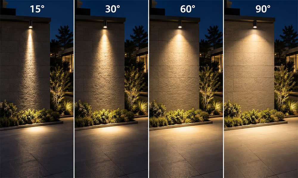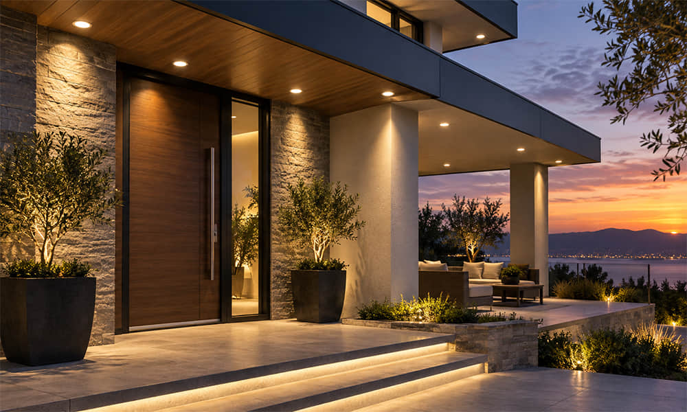
Dark light is commonly used in architectural lighting to describe a luminaire that reduces direct visibility of its bright LED source while still delivering useful light to the intended area. The visual goal is simple: see the illumination, not the light source.
However, dark light is a design concept rather than a universally defined product rating. Different manufacturers may use the term to describe different combinations of source recess, reflector or lens cut-off, black baffles, cellular louvers or controlled high-angle luminance. A dark-looking aperture alone does not prove low glare, and a concealed LED does not guarantee a low UGR result.
This guide explains what a dark light luminaire should control, which optical structures are relevant, and what should be checked before selecting a low-glare LED optic for a fixture.
What Does Dark Light Actually Control?
A successful dark light design limits direct views of high-luminance surfaces from normal observer positions. That may include the LED package, COB surface, reflector image, lens image or another bright part of the optical chamber.
| Design Objective | What It Means in Practice |
|---|---|
| Concealed LED source | The LED is recessed or shielded from expected viewing directions. |
| Controlled aperture brightness | The lens, reflector or opening does not become an excessively bright visual element. |
| Reduced high-angle output | Light is controlled in directions likely to enter an observer’s normal field of view. |
| Useful target illumination | The fixture still provides the required beam shape, illuminance and lighting uniformity. |
| Controlled reflections | Bright reflections on screens, glossy surfaces or surrounding materials are considered. |
Dark light can improve visual comfort, but it is not the same as “glare-free lighting.” Discomfort may still come from a small bright lens image, a reflector opening, a beam entering the line of sight, a glossy screen reflection or excessive contrast between the luminaire and its background.
How Dark Light Optics Work
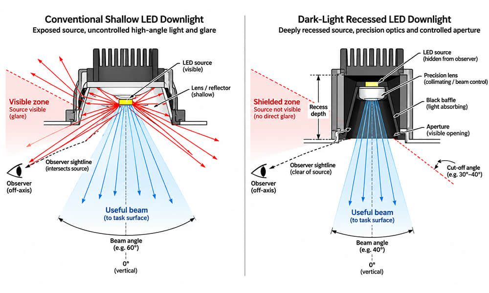
A dark light fixture usually relies on the combined effect of the LED position, optical system and luminaire aperture. The source is placed inside a recessed optical chamber; a lens or reflector redirects useful light toward the target; and the aperture geometry limits direct views of the source from selected angles.
Recess Depth and Source Position
Recessing the LED deeper into the fixture can increase physical shielding. The available depth must be balanced with optic height, aperture diameter, LED emitting-surface size, required beam angle and the overall luminaire profile.
A deeper recess may hide the LED more effectively, but it can also make the fixture larger or reduce useful light if the aperture, baffle or holder blocks part of the distribution.
Lenses and Reflectors Direct Useful Light
The optic must do more than restrict spill light. It must collect LED output and form a useful beam for the project: a narrow spot, medium distribution, wide flood, oval beam, linear aisle distribution or application-specific asymmetric pattern.
A TIR lens can provide compact beam control when matched correctly to the LED source and mechanical position. Reflectors are often practical for COB LEDs and deeper downlight or track-light structures. In either case, the final result depends on the completed luminaire rather than the optic alone.
Baffles and Louvers Limit Direct View
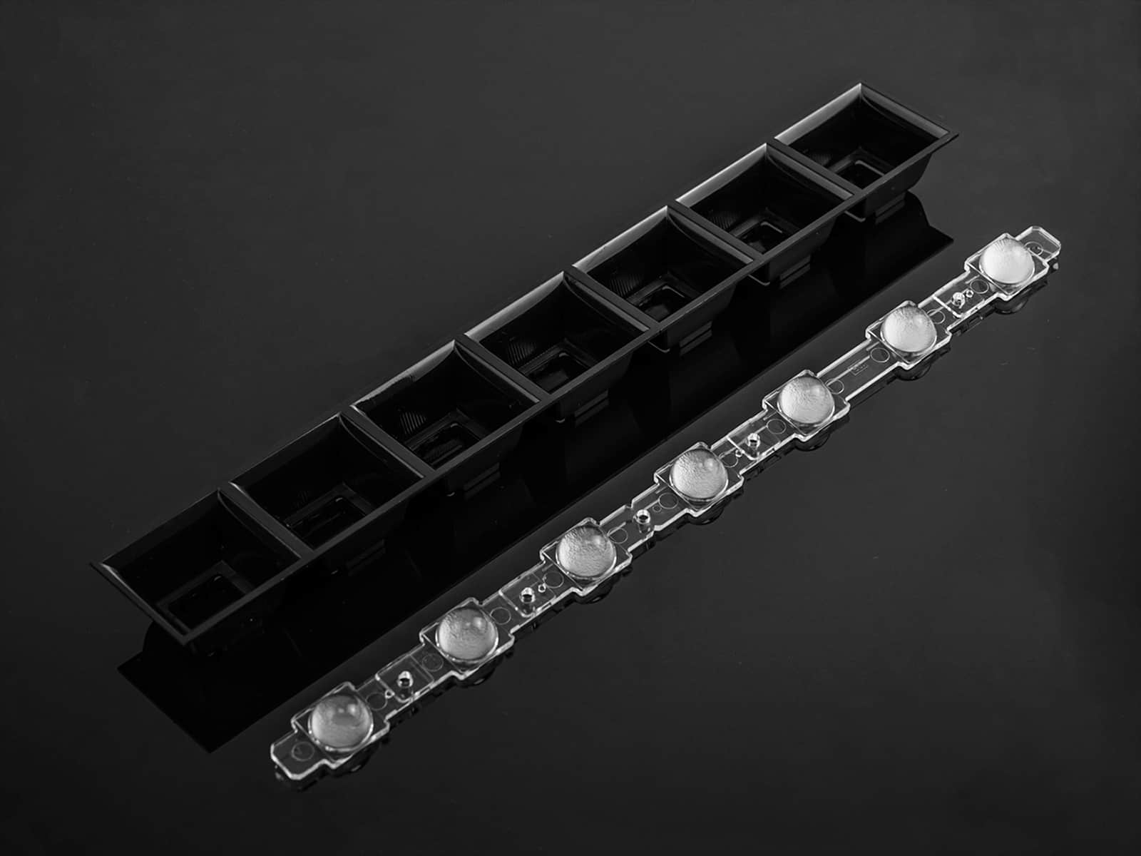
Black baffles, honeycomb accessories and cellular louvers can help block direct views toward the source and reduce unwanted internal reflections. They are useful supporting components, but they do not automatically create a low-glare fixture.
If the LED, lens image or reflector image remains visible from the observer position, changing the holder colour to black will not solve the underlying optical problem. A louver can also reduce transmitted flux, so its effect should be verified with photometric data.
Dark Light, Cut-Off, Beam Angle and UGR
These terms are often used together, but they should not be treated as interchangeable.
| Term | What It Describes |
|---|---|
| Dark light | A visual and optical design approach that reduces direct source visibility and keeps the luminaire visually unobtrusive. |
| Beam angle | The angular width of useful light distribution, often measured between the 50%-peak-intensity points. |
| Shielding or cut-off geometry | The physical relationship between the source, optic, aperture and observer direction. |
| High-angle intensity or luminance | How much light or brightness is present in directions where glare may occur. |
| UGR | An estimate of discomfort glare from a complete indoor lighting installation under defined conditions. |
Terms such as shielding angle and cut-off angle are not always measured from the same reference axis. Some documents use the downward vertical; others use the horizontal plane or a specific C-plane. A reliable datasheet should include a cross-section or photometric diagram showing the reference axis, luminous surface and observer direction rather than presenting an angle without context.
One well-known interpretation of Darklight technology is the alignment of the source cut-off with the reflector or lens cut-off, so the viewer is protected from direct reflections of the light source within that cut-off zone. ERCO’s Darklight reference illustrates this approach, but it should not be treated as the only industry definition of dark light.
Why Dark Light Is Not the Same as Low UGR
Dark light primarily concerns source concealment and the visual quietness of the luminaire. UGR lighting concerns discomfort glare from the complete installation. UGR is affected by luminaire luminance, apparent source size, fixture position, room dimensions, mounting height, spacing, observer position, viewing direction, background luminance and surface reflectance.
This is why an individual anti-glare LED lens does not have one universal UGR value. A lens may help a fixture achieve lower glare by reducing visible source brightness or high-angle output, but the final UGR belongs to the completed luminaire in a defined room calculation.
CIE 117 describes UGR as a practical discomfort-glare evaluation method that considers observer position and direction of view. For modern LED luminaires, another limitation matters: highly non-uniform bright sources may cause more discomfort than a simple average-luminance calculation suggests. CIE 232 discusses this issue for non-uniform LED source luminance.
Dark-Light Structures vs Other Glare-Control Approaches
Not every optical method that improves visual comfort should be described as dark light. The distinction helps fixture designers select the right structure for the project.
| Approach | Primary Function | Typical Use |
|---|---|---|
| Deep-recessed lens or reflector | Conceals the source through aperture geometry and controlled optical output. | Track lights, downlights and accent fixtures. |
| Shielded TIR optic | Controls the LED beam in a compact chamber while supporting source concealment. | Directional architectural lighting. |
| Cellular louver or honeycomb | Blocks high-angle views through individual shielded cells. | Offices, downlights and linear lighting. |
| Microprismatic optic | Redistributes light from a larger luminous surface. | Office and general linear lighting. |
| Diffuser | Improves visual uniformity and colour mixing. | Linear fixtures and broad-area illumination. |
| Indirect lighting | Removes direct source view by illuminating a ceiling or wall first. | Hospitality, offices and architectural ambient lighting. |
The first three structures are most directly associated with dark light because they focus on source shielding and aperture control. Microprismatic optics, diffusers and indirect lighting can improve visual comfort, but they do not necessarily conceal the luminous surface in the same way.
Where Is Dark Light Most Useful?
| Application | Important Observer Position | Primary Risk to Control |
|---|---|---|
| Office lighting | Horizontal sightlines and screen-facing views | Discomfort glare and reflected glare on screens. |
| Retail lighting | Customers moving through aisles and viewing displays | Bright track-light apertures, spill light and glare near merchandise. |
| Hotels and restaurants | Seated and low viewing positions | Visible bright points that interrupt atmosphere or visual comfort. |
| Museums and galleries | Viewpoints where the luminaire and exhibit enter the same field of view | The fixture competing visually with the displayed object. |
| Residential downlights | Seated, reclining and bed-level views | Insufficient recess depth causing direct LED visibility. |
How to Select a Dark Light LED Optic
Selecting by a phrase such as “low-glare lens” or “black reflector” is not enough. The optic must be evaluated together with the LED, fixture geometry and target area.
Prepare the following project information before screening existing optics:
- LED source: manufacturer, model, package size, LES dimensions, CCT, CRI and operating current.
- PCB and mechanical layout: LED position, PCB drawing, lens-to-LED distance, holder design, maximum optic diameter and available height.
- Target distribution: beam shape, target dimensions, working distance, mounting height, illuminance requirement and acceptable spill area.
- Glare-control objective: source concealment, defined aperture geometry, high-angle output limit, project UGR target or louver requirement.
- Application condition: indoor environment, material constraints, heat, UV exposure and any impact or IP requirement.
For compact spotlights, track lights and downlights, review available formats in our architectural LED lens range before assuming a new optic is required.
How to Validate a Dark Light Luminaire
Visual inspection is necessary, but a dark light claim should be verified using the intended production LED, PCB, holder, optic and luminaire structure.
- Confirm LED-to-optic position, recess depth and assembly tolerances.
- Measure the luminous-intensity distribution in relevant C-planes.
- Check high-angle intensity or luminance from realistic observer directions.
- Compare total luminous flux and useful target illuminance with the reference configuration.
- Inspect for hotspots, stray light, colour rings, bright lens images and reflector reflections.
- Generate IES or LDT data and calculate the intended lighting layout.
- Inspect the assembled fixture from standing, seated and reclining positions where relevant.
- Repeat key checks across multiple samples when production consistency is important.
When comparing two supplier solutions, make sure the LED model, drive current, thermal condition, fixture structure and test method are the same. Otherwise, apparent differences in glare or output may come from the test configuration rather than the optic.
Request a Dark Light Optic Evaluation
A good dark light solution balances source concealment, beam quality, useful optical output, mechanical space and the actual observer position. It should be evaluated as a complete luminaire system, not selected from a UGR label or baffle colour alone.
Send your LED model, PCB drawing, fixture cross-section, target area, working distance and glare-control requirement. Asahi can help screen suitable existing LED lenses and provide available optical drawings, beam information and photometric files for evaluation.