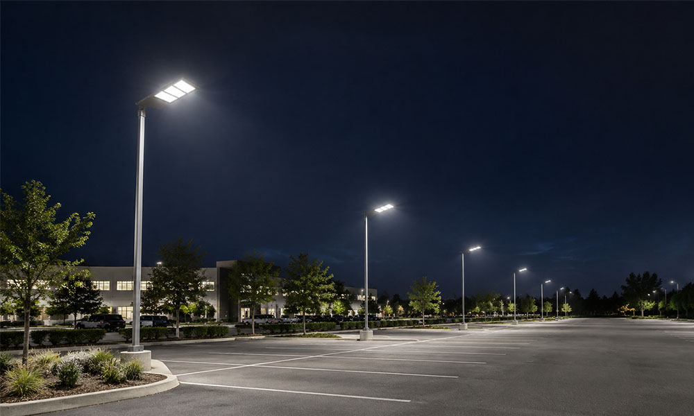
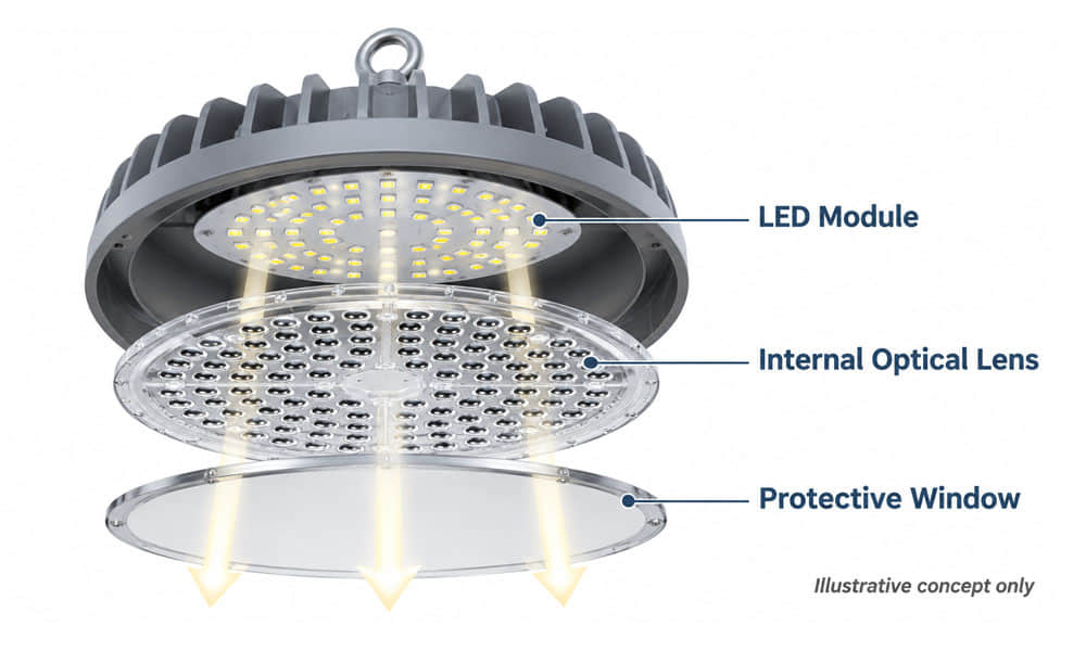
UFO LED lights can appear very bright while parts of a factory or warehouse remain too dark. The cause is not always insufficient lumens. The fixture’s light distribution, mounting height, spacing, obstructions or operating mode may prevent enough light from reaching the surface where it is needed.
Before increasing wattage or changing the lens, identify where the problem occurs. Then check the operating fixture, compare its photometric data with the actual installation and determine whether the issue calls for a layout change, maintenance or an optical review.
Why Can a Bright UFO LED Light Leave Dark Areas?
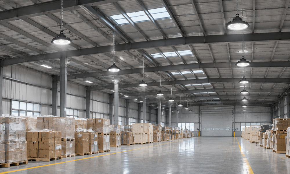
A bright-looking luminaire and a well-lit working area are not the same thing. The visible brightness of the source does not show how much light reaches the floor, a workbench or a vertical rack face.
For example, the floor directly beneath a UFO LED high bay light may appear bright, while the area halfway between adjacent fixtures receives much less light. In a warehouse, the floor may be adequately illuminated while a shelf label remains difficult to read because the label faces away from the strongest light or is blocked by racking.
Start by separating three questions:
- Is the fixture producing the expected output in its actual operating mode?
- Is the light distributed toward the surfaces that need illumination?
- Do the mounting positions and surrounding objects allow that light to reach them?
For the difference between light output and illuminance on a surface, see our guide to lumens, lux and luminous intensity.
Check the Operating Fixture Before Changing the Optic
If an existing installation appears darker than expected, first check whether the fixture is operating as intended. This can prevent an unnecessary lens or layout change.
- Check the control state: Confirm whether a schedule, occupancy sensor or dimming setting has reduced the output.
- Check the visible condition: Look for dust, contamination, damage or a visibly failed section. Cleaning and inspection should follow the manufacturer’s instructions and site safety procedures.
- Compare operating conditions: Record the control setting, relevant ambient conditions and whether the luminaire has reached a stable operating state.
- Compare with the requirement or baseline: Use the project’s specified lighting levels or comparable commissioning measurements, if available.
Without an initial measurement baseline, a current low lux reading cannot directly establish how much light has been lost since installation. Our article on evaluating LED brightness loss over time explains how operating hours and repeatable measurements help investigate the change.
Confirm That the Photometric File Matches the UFO High Bay Light
For a new layout or a retrofit comparison, use photometric data for the complete luminaire configuration, not just a generic file for the product family or an individual optical component.
Ask the fixture supplier to confirm that the IES or LDT file corresponds to:
- The quoted luminaire model and light-output setting.
- The installed optical version, cover and any relevant accessories.
- The intended mounting orientation.
- The operating mode being evaluated, including dimmed output where relevant.
Then check the lighting calculation: fixture positions, mounting heights, spacing, calculation area and maintenance assumptions should reflect the proposed installation. If racks or equipment are significant obstructions, discuss how they are represented in the assessment.
Two UFO LED lights with the same rated lumens can produce different results on the working surface. The U.S. Department of Energy’s industrial luminaire guidance also emphasizes evaluating the lighting needed for the application and comparing suitable complete products. Its purchasing thresholds apply to specified federal categories, not automatically to every project.
Identify Which Surface Needs More Light
Before choosing a different distribution, define the actual surface where the task is performed.
Open Floors and Workbenches
For an open factory floor, compare the specified average and minimum illuminance on the relevant horizontal working plane. Check points between luminaires and near the edge of the working area, not only the brightest point beneath a fixture.
A workbench may be evaluated at a different height from the floor. Use the plane and calculation area appropriate to the task and project requirements.
Warehouse Racks and Labels
For warehouse aisles, floor illuminance alone may not explain whether labels or goods are easy to see. Where the task requires it, evaluate illumination on the vertical rack face at the relevant positions, heights and directions.
Racks, stored goods and nearby fixtures affect the result. A lens change may be one option, but fixture placement or additional lighting may also need to be considered.
Equipment and Inspection Areas
At a machine or inspection station, equipment can block light even when the general area calculation looks acceptable. Identify the surface being inspected and the normal viewing direction before deciding whether general high-bay lighting is sufficient or separate task lighting is needed.
When Should You Review the Optic?
Use the observed mismatch to decide what to investigate. The lens is one possible part of the solution, but it should not be treated as the cause before the operating condition and geometry are understood.
| Observed Problem | Check First | Possible Next Step |
|---|---|---|
| Bright beneath fixtures, dark between them | Mounting height, spacing and complete-luminaire distribution. | Compare a different distribution or revise the layout. |
| Floor is adequate, rack labels are dark | Rack geometry, obstructions and vertical illuminance at the labels. | Evaluate the light reaching the rack face or consider an additional lighting arrangement. |
| Visible source feels uncomfortable | Viewing position, source visibility and fixture construction. | Review shielding and optical options against the required light output. |
| Fixtures with the same nominal angle look different | Complete intensity distribution, luminaire output and test conditions. | Compare matching photometric files rather than relying only on the angle label. |
A beam angle describes part of the distribution under a stated definition; it is not the boundary of all light or a guaranteed uniformly illuminated area. A fixture’s result must be considered with the actual layout.
A UFO Lens Example: Comparing Existing 184 mm Options
Consider an OEM developing a round UFO high bay light where the space between fixtures is darker than the project allows. If the housing and LED board can be matched to an existing optic, the manufacturer can compare candidate distributions before deciding whether a new optical design is needed.
Asahi’s UFO184D60G / UFO184D90G-100W-K56 lens series is one example to investigate. The product page lists:
- Diameter: 184 mm.
- Height: 7.69 mm.
- Material: PC-1250Z.
- Listed LED package types: 2835 and 3030.
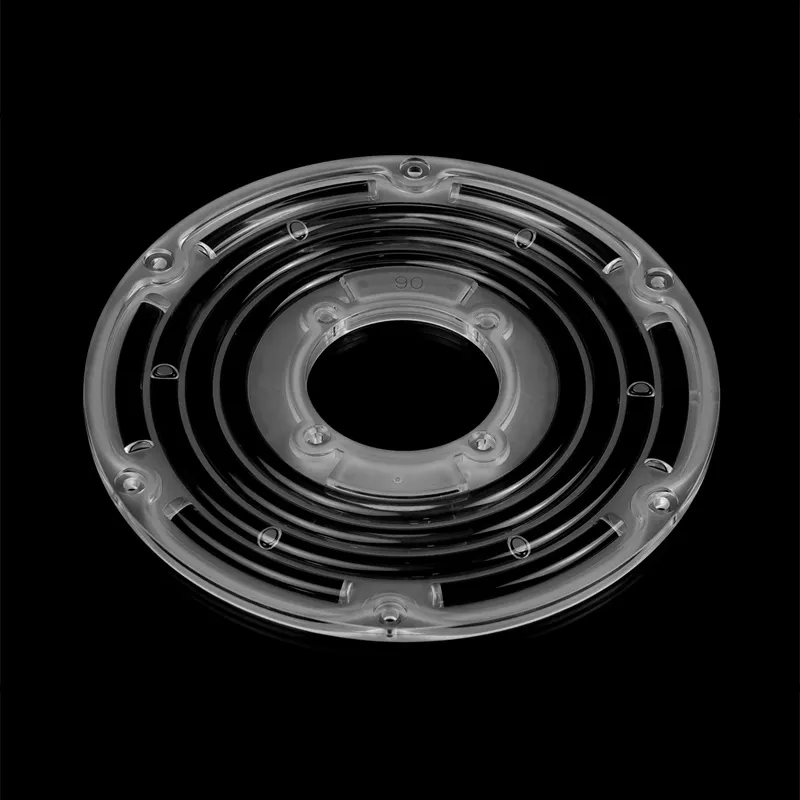
The product page provides drawings and separate photometric files labelled for different optical versions. The title and model line emphasize 60° and 90°, while the specifications and downloads also list a 120° version. Confirm the exact version, availability and file test conditions before comparison. These labels do not establish that one lens is adjustable between angles.
A practical evaluation would follow this sequence:
- Check mechanical fit: Compare the drawing with the housing clearance, mounting points and any components occupying the optical area.
- Check the LED board: Verify the actual LED part number, emitting area and PCB positions against the lens geometry. A 2835 or 3030 package label alone is not a complete compatibility check.
- Compare the optical versions: Review the available files and their test conditions, then evaluate the intended distributions using the same project geometry.
- Validate the finished fixture: Use representative complete-luminaire data and the proposed layout to compare the working-area and between-fixture results.
The product information identifies possible versions to evaluate; it does not show which version will solve a particular site’s dark area. No measured site comparison is implied, and a different distribution may also change output, glare or other aspects of the final result.
What Should Buyers Request Before Approving UFO LED Lights?
For a complete-fixture purchase, ask the supplier for information that matches the actual quotation and installation:
- Complete-luminaire photometric data for the quoted model, optical version and output setting.
- A lighting calculation using the proposed mounting height, positions and relevant working planes.
- Control settings and the expected output in each required operating mode.
- Environmental suitability, applicable safety documentation, maintenance information and warranty terms.
For a broader look at industrial applications and optical requirements, see our industrial lighting optics guide.
Discuss a UFO High Bay Optic with Asahi
For a new luminaire or an OEM redesign, send Asahi Optics the LED part number, PCB layout, available lens space, mounting height and the area or distribution that needs improvement. Existing drawings and complete-fixture photometric data are useful when available.
Contact Asahi Optics to identify existing lenses worth evaluating, apparent LED or mounting constraints, and the information needed for the next optical review. The assessment supports component selection; the completed luminaire and site layout still require their own verification.