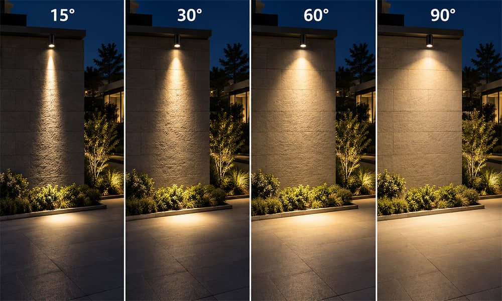
Choosing between a 15° vs 30° vs 60° vs 90° LED lens affects more than how wide the light appears. Beam angle influences target size, center intensity, fixture spacing, visual contrast, spill light and the tolerance required for LED-to-lens alignment.
A narrow beam can concentrate output onto a small target. A wide beam can distribute output across a broader area. Neither is automatically better. The correct LED lens beam angle depends on the LED source, target geometry, mounting distance, required illuminance and acceptable uniformity.
This article compares the practical roles of 15°, 30°, 60° and 90° optics. The numerical examples are geometric FWHM comparisons, not a substitute for measured photometric data from a completed luminaire.
What Does LED Lens Beam Angle Mean?
Beam angle is commonly specified as the angle between two directions where luminous intensity falls to 50% of the peak value. This is often called the full width at half maximum, or FWHM.
For an approximately circular and symmetric beam, the calculated diameter based on FWHM indicates the distance between the two 50%-peak-intensity points. It is not the zero-light boundary, the full illuminated area, the effective work area or a guarantee of acceptable uniformity.
For oval or asymmetric optics, one beam diameter is usually not enough. The distribution should be checked in at least the C0–C180 and C90–C270 planes, because beam width and intensity can differ significantly in each direction.
LED Lens Beam Angle Chart at a 3 m Mounting Distance
For a first geometric comparison, the estimated FWHM beam diameter can be calculated as follows:
FWHM Beam Diameter = 2 × Mounting Distance × tan(Beam Angle ÷ 2)
The following values assume a centered, circular beam and a 3 m distance from the lens to the target plane. Real LED photometric distributions are not ideal cones, so use these figures to compare beam-angle scale—not to determine final fixture spacing or guaranteed coverage.
| Nominal Beam Angle | Estimated FWHM Beam Diameter at 3 m | Typical Starting Use | Primary Risk to Check |
|---|---|---|---|
| 15° | Approx. 0.79 m | Narrow accents, focused façade lighting and long-throw spotlight effects | Alignment sensitivity and limited target width |
| 30° | Approx. 1.61 m | Retail displays, track lights, artwork and focused downlights | Target edges may receive much less light than the center |
| 60° | Approx. 3.46 m | General directional lighting and medium-height interior applications | Fixture spacing and overlap determine uniformity |
| 90° | Approx. 6.00 m | Wide short-throw coverage and broad-area lighting | Lower center intensity and increased spill outside the target |
The calculated FWHM diameter of a 90° beam is about 7.6 times larger than that of a 15° beam at the same distance. Because the corresponding beam area increases much more rapidly, the same luminous flux is distributed far more broadly. Actual center intensity, however, must be confirmed from measured photometric data.
15° LED Lens: Focused Light for Narrow Targets
A 15° LED lens is normally selected when the fixture must create a concentrated beam with strong visual emphasis. It can be suitable for narrow vertical targets, high-wall accent lighting, focused façade lighting, display lighting, signage and grazing effects.
The benefit is strong directional control. The trade-off is that narrow optics are more sensitive to LED position, lens height, holder tolerances and fixture aiming. A small lateral offset can make the beam appear off-center, particularly when the target is far from the fixture.
For narrow-beam projects, the LED emitting surface should be checked carefully. A lens tested with a small 3535 LED may produce a wider or less-defined result when paired with a larger LED source. For available narrow, medium and wide circular distributions, see our architectural single LED lens range.
30° LED Lens: A Useful Starting Point for Accent Lighting
A 30° LED lens is often used where the target needs more coverage than a narrow spot can provide, while still retaining a defined beam. Typical applications include track lights, retail displays, artwork illumination, shelving and focused downlights.
Example: A 1.5 m Retail Display at 3 m Distance
For a display approximately 1.5 m wide and a fixture positioned 3 m away, a 30° optic produces an estimated FWHM diameter of about 1.61 m. Geometrically, this makes 30° a reasonable optical starting point for evaluation.
However, matching the target width to the calculated FWHM diameter does not guarantee uniform illumination. At the calculated beam edge, luminous intensity is already near 50% of the peak value. The target edges may receive substantially less illuminance than the center, especially when the fixture is aimed at an angle instead of perpendicular to the target.
The final decision also depends on total luminous flux, target height, beam position, installation angle, desired edge brightness and overlap from adjacent fixtures. A 15° optic may leave the display edges underlit, while a 60° optic may create unnecessary spill onto adjacent merchandise.
60° LED Lens: Broader Coverage with Directional Control
A 60° LED lens is often a practical option for general directional lighting where a 30° beam is too concentrated but a 90° beam is too broad. It may be used in commercial interiors, retail aisles, hospitality spaces, general downlights and medium-height installations.
At the same mounting distance, a 60° optic creates a much larger FWHM area than a 30° optic. This can support wider fixture spacing, but only if the luminaires still overlap correctly on the target plane. Wide spacing can create dark areas between fixtures; overly close spacing can create excessive overlap and uneven brightness.
90° LED Lens: Wide Distribution for Broad Target Areas
A 90° LED lens is intended for broad coverage, particularly where fixtures are mounted closer to the target or where the priority is general-area illumination rather than a narrow visual accent.
Lower center intensity does not necessarily mean lower optical efficiency. Much of the output may simply be distributed over a wider angle. Total transmitted flux should be measured separately, because optical efficiency can also be affected by lens material, surface design, Fresnel losses, cutoff features and the amount of light leaving outside the useful target area.
For a dedicated explanation of wide-angle applications, see our guide to 90° LED lens light coverage.
Why the LED Package Changes the Final Beam
Beam angle belongs to the complete optical system, not to the lens alone. A real LED has an emitting area with physical width, height and angular color characteristics. When the source becomes larger, light enters the lens from more positions and directions, making a very narrow output beam more difficult to achieve with a compact optic.
This is especially important for 15° and 30° optics. A larger emitting surface can widen the measured FWHM, soften the beam edge, reduce peak intensity or change the visible color pattern. PCB placement, holder design and the distance between the LED emitting surface and the lens reference surface also affect the final distribution.
For an explanation of how compact optics combine refraction and internal reflection for beam control, see our guide to TIR lenses and LED beam control.
How to Compare Supplier Beam-Angle Data
When comparing 15°, 30°, 60° and 90° lens data from different suppliers, confirm that the products were measured using the same LED, drive current, thermal condition, mounting structure and test method. A beam-angle label alone is not enough for a direct comparison.
| Data to Compare | Why It Matters |
|---|---|
| LED model and drive current | Confirms whether the source output and emitting area are comparable. |
| FWHM in C0–C180 and C90–C270 planes | Shows whether the beam is circular, oval or asymmetric rather than relying on one nominal angle. |
| Peak candela | Shows center-beam intensity when input conditions are identical. |
| Total luminous flux | Shows how much light is transmitted through the tested module or fixture. |
| Peak cd/lm | Helps distinguish a more concentrated distribution from a result caused only by higher total luminous flux. |
| Polar intensity curve | Shows beam symmetry, side lobes, spill light and the shape of the actual distribution. |
| Target-plane illuminance map | Shows whether the intended mounting height and spacing deliver suitable coverage and uniformity. |
| Beam image or spot photograph | Helps identify visible hotspotting, color rings, beam shift and edge quality. |
When reviewing beam images and polar curves, confirm that they were measured using the same LED, drive current, mounting condition and test distance. Otherwise, differences may come from the test setup rather than the optic itself.
When a Circular Beam Is Not the Right Optical Solution
15°, 30°, 60° and 90° are useful comparisons for circular-beam optics, but some applications require a different distribution type. A long rectangular target may need an oval beam. A wall-wash luminaire may need dedicated asymmetric optics to control vertical distribution and reduce scalloping. Roadway lighting requires application-specific asymmetric distributions rather than a standard circular beam.
For road and area projects, review dedicated street and area lighting optics. These products are designed around roadway, area-lighting or outdoor target geometry rather than circular spotlight coverage.
Quick Guide: Which LED Lens Beam Angle Should You Start With?
| If Your Priority Is... | Potential Starting Point |
|---|---|
| Focused light on a narrow or distant target | 15° or another narrow-beam optic |
| Accent lighting with defined target coverage | 30° optic |
| General directional lighting with broader coverage | 60° optic |
| Broad coverage at a short mounting distance | 90° or wider optic |
| Wall washing, rectangular targets or roadway distribution | Oval, asymmetric or application-specific optic |
Request an LED Lens Recommendation
To screen an existing optic efficiently, provide the LED model and datasheet, LED quantity, PCB layout, target dimensions, mounting height or working distance, required illuminance and intended application.
If available, include a fixture cross-section, holder drawing, target-plane layout, polar curve, IES file or spacing plan. Based on these inputs, Asahi can screen compatible LED lenses and provide available drawings, beam-angle data, distribution images and photometric files for evaluation.