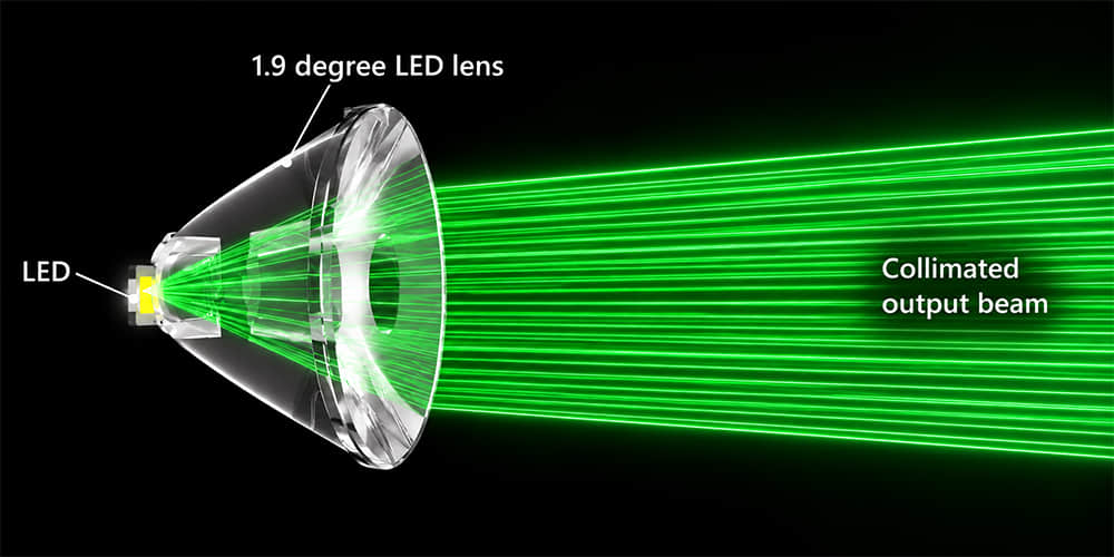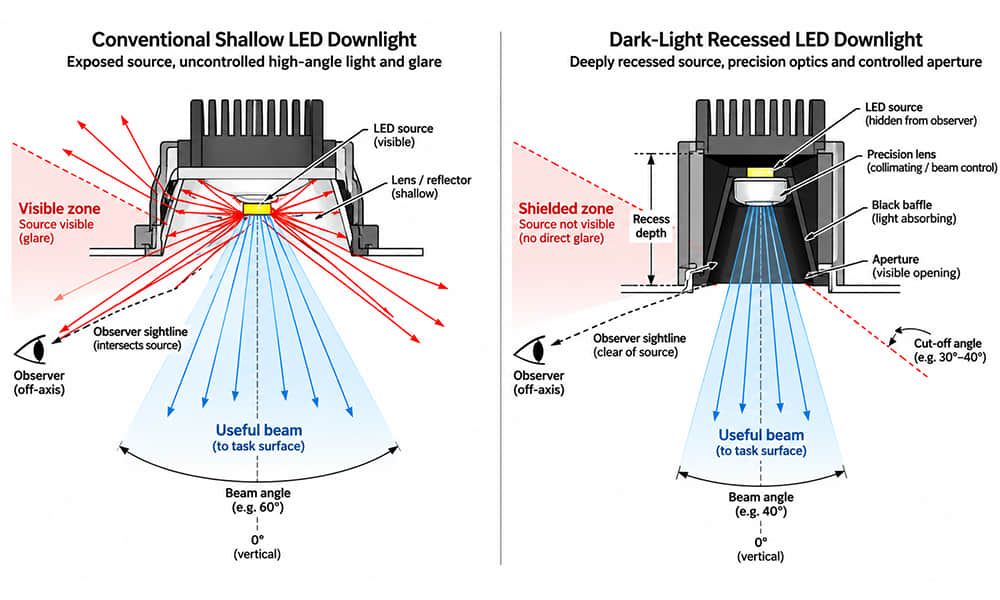
Bridge lighting combines several different visual tasks: helping drivers see the road, supporting pedestrians and cyclists, revealing architectural structures, and preserving the visibility of navigation signals. These tasks should not be treated as one large floodlighting project.
A distribution that highlights an arch may create glare for approaching drivers. A narrow spotlight that reaches a bridge tower may miss a moving cable. A visually attractive waterfront scene may also send unnecessary light into the river. Selecting optics therefore starts with the target geometry, observer positions and project restrictions—not simply a beam-angle label.
For luminaire manufacturers selecting LED lenses, this guide connects those project conditions to practical optical decisions, including roadway distributions, oblique projection, cable aiming tolerance and photometric verification.
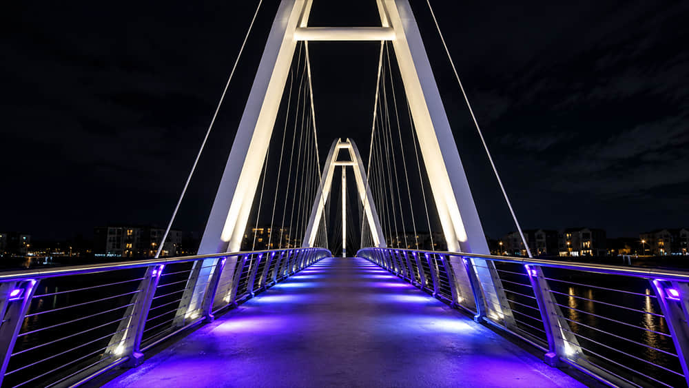
1. Define the Lighting Task Before Selecting Optics
Separate the bridge into functional, architectural and protected zones. Record which surfaces must receive light, which viewing directions must remain comfortable, and which areas must remain dark. For bridges over navigable water, confirm the regulatory boundaries before deciding on decorative colors, dynamic effects or operating hours.
Vehicle Decks: Roadway Performance Is More Than Lux
CIE 115: Lighting of Roads for Motor and Pedestrian Traffic distinguishes motorized traffic, conflict areas and pedestrian areas through different lighting classes. The applicable national standard and project authority determine the class and acceptance criteria; there is no single lighting level suitable for every bridge.
For a vehicle deck evaluated using road luminance, the relevant questions include how bright the pavement appears from the prescribed driver positions, how consistently that brightness is maintained, and whether the lighting reduces visibility through disability glare.
| Criterion | What It Evaluates | Optical and Layout Implications |
|---|---|---|
| Average road luminance | The average pavement luminance seen from specified observer positions, expressed in cd/m². | Select the intensity distribution together with the pavement reflection characteristics, mounting position and luminaire spacing. |
| Overall uniformity, Uo | Minimum road luminance divided by average road luminance over the specified calculation area. | Check dark areas between luminaires, near barriers and across the lane width rather than optimizing only the brightest points. |
| Longitudinal uniformity, Ul | Minimum-to-maximum luminance along specified longitudinal calculation lines. | Control repeated bright and dark bands along the direction of travel through distribution shape, spacing and mounting geometry. |
| Threshold increment, TI | A measure used to assess disability glare and its effect on visibility under the specified road-lighting calculation conditions. | Limit intensity toward relevant driver sightlines. A high-output optic is not acceptable simply because it raises road luminance. |
| Surround or edge illumination | Lighting immediately outside the carriageway, using the metric required by the adopted standard. | Balance road-edge visibility with restrictions on light entering water, adjacent properties or environmentally sensitive areas. |
| Wet-road performance, where required | Performance under the wet-pavement conditions specified for the project. | Evaluate the prescribed wet-road reflection conditions; a dry-road calculation alone may not reveal concentrated reflections or reduced uniformity. |
Some specifications use a surround ratio, while others use an edge illuminance ratio. These terms should not be substituted without checking their definitions and calculation areas. Likewise, a horizontal illuminance map cannot by itself establish compliance with a luminance-based roadway class.
For bridge deck lighting, evaluate an asymmetric street and area lighting distribution in the actual lane geometry. Include parapets, barriers, fixture setback, tilt and the transition to the approach road. A nominal road-distribution type is a screening tool, not a completed lighting design.
Conflict Areas, Pedestrian Paths and Cycle Routes
Junctions, crossings and other conflict areas may use illuminance-based criteria under the adopted standard. Pedestrian and cycle routes also need their own assessment rather than inheriting the vehicle-deck requirements.
Horizontal illuminance helps describe the light reaching the walking surface. Where required, vertical or semicylindrical illuminance addresses additional visual tasks, including seeing approaching people and recognizing faces. A railing-mounted luminaire can illuminate the pavement effectively while leaving faces poorly lit—or expose a bright source directly to pedestrians.
Check the relevant directions and heights of these evaluation surfaces. Stairs, landings and changes in level should also be examined for shadowing caused by the railing or bridge structure.
2. Match the Distribution to the Structure and Installation Geometry
Architectural bridge lighting should reveal the intended structure without treating every element as a spotlight target. The same pier or arch may require different optics when the mounting position changes.
| Bridge Element | Distributions Worth Comparing | Decisive Project Conditions |
|---|---|---|
| Vehicle deck and approaches | Controlled asymmetric road distributions. | Lighting class, lane geometry, pavement reflection, spacing, barriers and driver glare. |
| Pedestrian and cycle areas | Controlled asymmetric or broad distributions with appropriate shielding. | Path width, vertical-lighting requirements, mounting height and direct source visibility. |
| Piers and towers | Spot, oval or asymmetric distributions; multiple aiming zones where necessary. | Surface height and width, setback, oblique incidence, near-to-far illuminance variation and surface reflectance. |
| Arches and trusses | Oval beams, segmented spot lighting or integrated linear lighting. | Curvature, structural interruptions, fixture spacing and continuity between illuminated sections. |
| Cables | Narrow or moderately wider spots, oval distributions, integrated lighting or overlapping fixtures. | Projected cable width, inclination, throw distance, movement, aiming tolerance and permitted spill light. |
| Railings and structural outlines | Shielded linear or asymmetric distributions. | Continuity, pedestrian sightlines, visible LED images and light escaping beyond the bridge edge. |
| Under-bridge spaces | Controlled broad or asymmetric distributions, depending on the target. | Whether the task is lighting a public route, revealing the soffit or illuminating a vertical surface. |
For piers and broad vertical surfaces, the distinction between accent lighting and uniform surface lighting matters. A narrow beam can emphasize a selected section of a tower, but it is not automatically a wall-washing solution. The fixture setback, upper-surface intensity and overlap requirements are discussed separately in our wall wash lighting application guide.
Why Cable Lighting Does Not Always Need the Narrowest Beam
A cable is slender, but it is also long, inclined and potentially moving. A very narrow circular beam may illuminate only a short section or miss the cable after a small aiming change. Increasing peak intensity does not solve that geometrical problem.
For bridge cable lighting, compare the projected target width with the intensity distribution at the actual throw distance. Include installation tolerance and the movement envelope supplied by the structural team. An oval beam can extend along a cable while keeping the cross-cable spread controlled; a slightly wider beam can provide aiming margin, although it may increase spill light.
Close-mounted integrated lighting or several overlapping fixtures may be preferable when a distant projector cannot remain accurately aligned. The decision should follow the target geometry and permitted light outside the cable—not the component name alone.
3. Account for Oblique Projection Before Using Beam-Angle Calculations
Bridge piers, towers, arches and cables are commonly illuminated at an angle. Under these conditions, mounting height is not the throw distance, and a circular angular distribution does not create a circular footprint on the target.
What Changes When the Beam Strikes at an Angle?
- The footprint stretches along the plane of incidence.
- The near and far parts of the target have different source-to-surface distances.
- Illuminance changes with the angle between the incident ray and the local surface normal.
- A small aiming adjustment can produce a substantial movement on a distant or steeply illuminated surface.
An ideal circular cone intersecting a plane can form an ellipse when the geometry produces a bounded intersection. Real photometric distributions, curved piers and inclined cables can produce more complicated patterns.
For a target plane perpendicular to the optical axis, a geometric estimate is:
D = 2r × tan(θ / 2)
Here, r is the axial distance and θ is the full beam angle. If the supplied angle is FWHM, the result describes the spacing between the corresponding 50%-peak-intensity directions on that perpendicular plane. It is not a boundary beyond which no light exists, nor a guarantee of useful or uniform illumination.
Calculated Example: A Projector Aimed Up a Vertical Bridge Pier
Consider a projector located 4.00 m horizontally from a flat, vertical pier face. Its aiming point is 6.00 m above the projector’s optical center. The central throw distance is:
r = √(4² + 6²) = 7.21 m
The central incidence angle is approximately 56.3° from the surface normal. It is not measured from the surface itself.
For an assumed circular FWHM distribution, the lower and upper boundary-ray intersections in the vertical plane of incidence are:
hlower = a × tan(α − θ / 2)
hupper = a × tan(α + θ / 2)
In this example, a = 4.00 m and α = 56.3°. All intersection heights below are measured above the projector’s optical center.
| Assumed Full FWHM Angle | Lower Intersection | Upper Intersection | Vertical Span |
|---|---|---|---|
| 5° | 5.47 m | 6.61 m | 1.14 m |
| 10° | 4.99 m | 7.31 m | 2.31 m |
| 15° | 4.57 m | 8.13 m | 3.56 m |
At 7.21 m, the perpendicular-plane estimate for a 10° beam is approximately 1.26 m. On this obliquely illuminated pier, the corresponding vertical span is approximately 2.31 m and is not symmetric around the 6.00 m aiming point.
These are intensity-direction intersections, not a 50%-illuminance contour on the pier. The distance and incidence angle change across the surface, so the illuminance at those two intersections will not necessarily be equal.
Calculate Illuminance Using the Actual Distance and Surface Normal
For a point-source or far-field approximation, direct illuminance at a surface point can be estimated as:
E(P) = I(P) × cos α(P) / r(P)²
- I(P): luminous intensity toward that point, in candela, obtained from the correctly oriented photometric distribution.
- r(P): actual straight-line distance from the luminaire to the point, in meters.
- α(P): angle between the incident ray and the local surface normal.
The result is in lux. This approximation excludes reflected light, obstruction and other losses.
At the center of the example pier, cos 56.3° is approximately 0.555. If the intensity toward that point were an assumed 1,000 cd, the calculated direct illuminance would be approximately 10.7 lx. At the same distance under normal incidence, it would be approximately 19.2 lx. These figures illustrate geometry only; they are not Asahi product test results.
A stretched footprint therefore does not mean that the far end receives sufficient light. Depending on the target, an asymmetric distribution, a second aiming zone or a different mounting position may provide a better result than simply widening a circular beam.
Include Aiming Tolerance in the Design
With the same 4.00 m setback, increasing the aiming angle by 1° moves the central intersection approximately 0.23 m upward. Decreasing it by 1° moves the intersection approximately 0.22 m downward.
For a slender cable or a narrow architectural detail, that displacement can be larger than the target width. Model the permitted bracket-angle variation and structural movement, rather than checking only the nominal aiming position.
4. Use Published Photometric Data to Check Beam Orientation
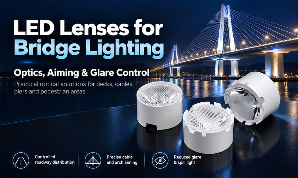
An oval distribution can be useful for an elongated bridge element, but the broad and narrow axes must be correctly assigned in the lighting model and during installation.
Asahi’s AF Series architectural optics have a listed diameter of 21.3 mm and height of 12.34 mm, using a PMMA lens with a PC holder. Published distribution options include circular beams and oval versions such as 10×45°, 10×60° and 30×60°. These provide candidates for geometry-based evaluation, rather than automatic recommendations for every bridge surface.
A Traceable Example from an Existing IES File
The table below uses values extracted from the publicly available AF Series 10×45° IES file. Each column is normalized to the on-axis intensity in its own C-plane:
Relative intensity = I(C, γ) / I(C, 0°) × 100%
| Angle from the Photometric Axis, γ | C = 0° Direction | C = 90° Direction |
|---|---|---|
| 0° | 100.0% | 100.0% |
| 10° | 23.2% | 94.4% |
| 20° | 6.3% | 65.6% |
| 30° | 2.7% | 19.0% |
At 20° off-axis, the file retains approximately 65.6% of its on-axis intensity in the C = 90° direction, compared with 6.3% in the C = 0° direction. That difference explains why rotating an oval distribution can substantially change the amount of light sent along or across a structural element.
Confirm how the photometric axes correspond to the physical lens and mounting references before installation. Do not assume that a housing mark identifies the broad axis without checking the drawing and photometric orientation.
This is an analysis of an existing exported distribution, not a same-condition comparison between luminaires. The export does not identify the LED model, drive current or thermal conditions, so these ratios should not be used to claim complete-luminaire output, optical efficiency or performance with a different LED.
5. Assess Glare from the Actual Observer Positions
For LED bridge lighting, glare assessment should include the people who use the bridge and the surrounding transport routes—not only a distant architectural viewpoint.
- Drivers: check the prescribed roadway observer positions, both travel directions, approach gradients and visibility of decorative projectors.
- Pedestrians and cyclists: examine direct source visibility, stairs, railing-mounted fixtures and transitions between bright and dark areas.
- Vessel operators: assess approaching-channel sightlines, navigation-signal visibility and glare from fixtures mounted near the water.
- Nearby residents: check light entering windows and the brightness of visible illuminated surfaces.
A narrow beam can still produce severe glare if a viewer looks into its high-intensity direction. Recessing the source, adding suitable shielding or relocating the fixture may be more effective than reducing beam width.
Roadway TI calculations address a defined disability-glare task. Indoor UGR values or a “hidden light source” description cannot replace that evaluation, and TI should not be presented as a universal rating for architectural floodlighting.
Assess the complete night scene as well as the roadway calculation. Decorative luminaires and bright structural surfaces can affect the visual background even when the road-lighting system itself meets its specified criteria.
6. Protect Waterways and Ecologically Sensitive Areas
Waterfront bridge illumination requires more than controlling visible reflections. Light can reach the water directly, illuminate bankside habitats and alter dark routes used by wildlife.
CIE 150: Guide on the Limitation of the Effects of Obtrusive Light provides a framework for assessing and limiting outdoor lighting impacts. Project-specific ecological restrictions still depend on the location, affected habitats, species and environmental assessment.
Evaluate Direction, Spectrum and Operating Time Together
- Direction: identify rays that miss the bridge structure and reach the water, banks, vegetation or sky.
- Spectrum: obtain spectral power distribution information where ecological assessment requires it. CCT alone does not describe the full spectrum.
- Exposure: assess the amount of light reaching sensitive areas and how long it remains present.
- Operation: establish approved dimming levels, architectural-lighting curfews and seasonal restrictions where applicable.
- Dynamic scenes: review RGBW colors, transitions and operating schedules rather than approving only one static white-light scene.
Fish, insects, birds and bats do not necessarily respond to the same spectral or temporal conditions. A warm-white or red scene should not be described as universally wildlife-safe. The ecological team should define the relevant constraints before the lighting supplier selects a color recipe.
Where possible, maintain dark water and habitat zones through mounting position, shielding and distributions that intercept the intended structure. Dimming cannot correct a beam aimed into a protected area.
Architectural lighting can have a separate control schedule from functional lighting. Any reduction to road or pedestrian lighting must remain consistent with the approved safety requirements.
7. Keep Decorative Lighting Separate from Navigation Signals
For a bridge crossing navigable water, establish the protected signal positions and vessel viewing directions before approving architectural colors or effects. Decorative lighting must not obscure required signals, make them difficult to distinguish, or create misleading signal-like patterns.
As a jurisdiction-specific example, United States 33 CFR Part 118 prohibits interference with prescribed bridge lights and signals. It also requires approval of the required lights and signals before construction. The rules include red and green navigation markings for relevant bridge configurations; they are not a general decorative-lighting specification for projects worldwide.
Elsewhere, consult the responsible navigation or maritime authority and the applicable local requirements. Road authorities, planning departments, environmental agencies and heritage bodies may also need to review parts of the proposal.
Provide reviewers with fixture positions, aiming directions, proposed colors, dynamic behavior and operating hours. Particular attention should be given to bright backgrounds behind navigation lights, direct glare toward the channel and red or green decorative effects that could be confused with signals.
Keep mandatory navigation lighting operational independently of architectural scenes and curfews, in accordance with the applicable authority’s requirements.
8. Compare Candidate Optics in a Bridge-Specific Model
A useful comparison holds the project geometry constant and changes the candidate distribution. Build the model from the bridge drawings, including target surfaces, fixture coordinates, obstructions, road geometry and protected zones.
Use our guide to reading IES files for lens selection for file interpretation. For a controlled comparison, also confirm the LED, current, thermal condition, lens orientation and luminaire configuration behind each dataset.
| Comparison Item | Why It Matters |
|---|---|
| Total emitted lumens, peak candela and peak cd/lm | Separates total output from directional concentration when datasets have compatible test conditions. |
| Full intensity distribution and relevant C-plane sections | Reveals beam orientation, asymmetry and intensity outside the main beam that a single angle cannot describe. |
| Target-plane illuminance and surface luminance | Shows near-to-far variation, dark regions and the visual effect of surface reflection. Roadway luminance requires the prescribed road-reflection model. |
| Light reaching the intended target and protected zones | Distinguishes useful delivery from light entering water, the sky, windows or transport sightlines. |
| Aiming-tolerance cases | Checks whether acceptable performance survives the permitted installation error and structural movement. |
| RGBW channels and approved operating scenes | Checks color-dependent distribution, mixing and environmental or navigation restrictions. |
If reporting a spill-light percentage, define its denominator and the measurement or simulation boundary. A calculated percentage of emitted flux missing a pier is not the same metric as illuminance measured on the water or intensity toward an observer.
Use a Representative Mock-Up Before Finalizing the Installation
A pier or cable mock-up should use the proposed LED, optics, housing, protective window and bracket. Record aiming coordinates and compare target-plane measurements with the model. For beam photographs, keep camera position, exposure and white balance fixed; automatically exposed images cannot support a fair brightness comparison.
For a pier with a bright base and dark upper section, inspect the individual fixtures separately before changing the whole system. Check whether the problem follows distance, distribution orientation, obstruction or aiming. For repeated gaps along an arch, compare beam overlap at the real curved surface rather than on an imaginary flat plane.
This process helps identify whether a different optic is needed or whether the mounting position, orientation or spacing is the main cause.
9. Maintain Optical Alignment in the Outdoor Environment
The selected distribution must remain correctly aligned after installation. Bracket movement, thermal expansion, lens-to-LED displacement and protective-window changes can alter the projected pattern.
Specify suitable materials for the actual UV exposure, temperature, cleaning chemicals and coastal environment. Our comparison of PC, PMMA and glass lens materials explains the material-selection considerations without treating one material as the answer to every outdoor project.
Ingress protection, impact resistance and corrosion performance belong to the complete luminaire construction. A lens material or component specification does not establish an assembled fixture’s IP or IK rating.
Request an Existing Lens Recommendation for Your Bridge Lighting Project
To shortlist bridge lighting optics, send Asahi the target dimensions and bridge-element drawings, fixture coordinates, aiming direction, LED model, emitting-area information, PCB layout and available optical space. Include the required roadway class or target-surface criteria, together with restrictions for drivers, water, wildlife and navigation signals.
PDF drawings, CAD files and existing IES or LDT data can help communicate the project. Specify the required illuminated area and permitted dark zones; provide a preferred beam angle if available, but do not use it as the only selection criterion.
Asahi can review compatible existing optics and discuss relevant mechanical drawings, available photometric files and sample options for the shortlisted models. If existing distributions do not fit the geometry, the project can move to an optical design review. Final lighting compliance and approval remain with the responsible project designers and authorities.