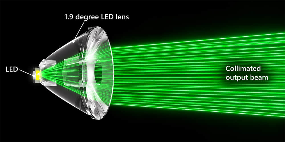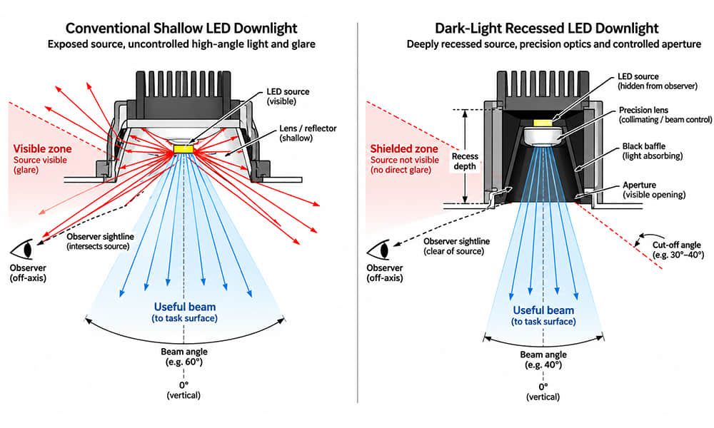
LED lens cracking does not always begin with a visibly defective component. A transparent optical lens may pass incoming inspection and appear normal during assembly, but fine white lines, surface crazing or complete cracks can develop after screw tightening, cleaning, temperature testing or luminaire operation.
This delayed failure usually occurs because several forms of stress act on the lens at the same time. An injection-molded lens may contain residual stress. Assembly adds mechanical force, while LED heat, thermal cycling or an incompatible chemical further reduces the material’s resistance to cracking.
Asahi Optics develops and manufactures LED lenses for outdoor, industrial, indoor, automotive and other lighting systems. Based on these different operating conditions, identifying the source of a crack requires more than replacing the damaged part. A useful investigation should determine:
- Where the damage began;
- When it first became visible;
- Which mechanical, thermal or chemical factors affected that area;
- Whether the failure follows a material batch, mold cavity, assembly station or luminaire structure.
What Does LED Lens Cracking Look Like?
Not every white line on a plastic optical lens is a structural crack. Before changing the material, mold or luminaire design, identify the type and location of the defect.
Complete Cracks
A complete crack is a fracture extending into or through the lens material. It may begin at an edge, mounting hole, locating pin, optical cell or sudden thickness transition.
A structural crack may affect mechanical strength, waterproof sealing, lens position and light distribution. If it reaches a sealing surface or crosses an optical cell, the lens should not normally be approved for production.
Lens Crazing
Lens crazing appears as a network of fine surface lines. Under normal lighting, the affected region may look cloudy, frosted or white. Under directional light or magnification, many short hairline features become visible.
Crazing is frequently associated with tensile stress combined with chemical exposure. For example, a lens may remain clear after assembly but develop fine white lines around a screw boss after contact with an unsuitable cleaner.
Scratches and Abrasion
Scratches result from contact with dust, tools, packaging or rough cleaning materials. They often follow the direction of movement and remain close to the surface.
A scratch can reduce optical quality, but it does not necessarily indicate structural failure. Crazing generally forms a branching or web-like pattern and may appear without obvious physical contact.
Molding Lines and Stress Patterns
Some visible lines originate during injection molding but are not open cracks. Flow marks, weld lines and birefringence patterns may become visible under certain viewing conditions.
Magnification and polarized-light inspection can help distinguish molding features from physical fractures.
Cracks, Crazing and Scratches: Quick Comparison
| Condition | Typical appearance | Possible cause | First check |
|---|---|---|---|
| Structural crack | Continuous fracture extending into the material | Mechanical load, impact, residual stress or thermal cycling | Inspect the crack origin and depth |
| Crazing | Fine white or web-like surface lines | Chemical exposure combined with tensile stress | Review cleaners, sealants, adhesives and assembly load |
| Scratch | Directional surface groove | Handling, tools, dust or abrasive cloth | Review packaging and cleaning procedures |
| Weld or flow line | Repeated line at the same molded position | Material flow, gate position or process conditions | Compare parts from each mold cavity |
| Birefringence pattern | Colored or bright pattern under polarized light | Molded-in residual stress | Compare stress patterns by cavity and process |
Why LED Lenses Crack After Installation
Most delayed failures are not caused by one isolated factor. They occur when several types of stress overlap at the same location.
Total lens stress = molded-in stress + assembly stress + thermal stress + chemical or environmental effects
A lens may tolerate one factor independently but crack when mechanical force, heat and chemical exposure act together.
1. Overtightened Screws and Uneven Fastening
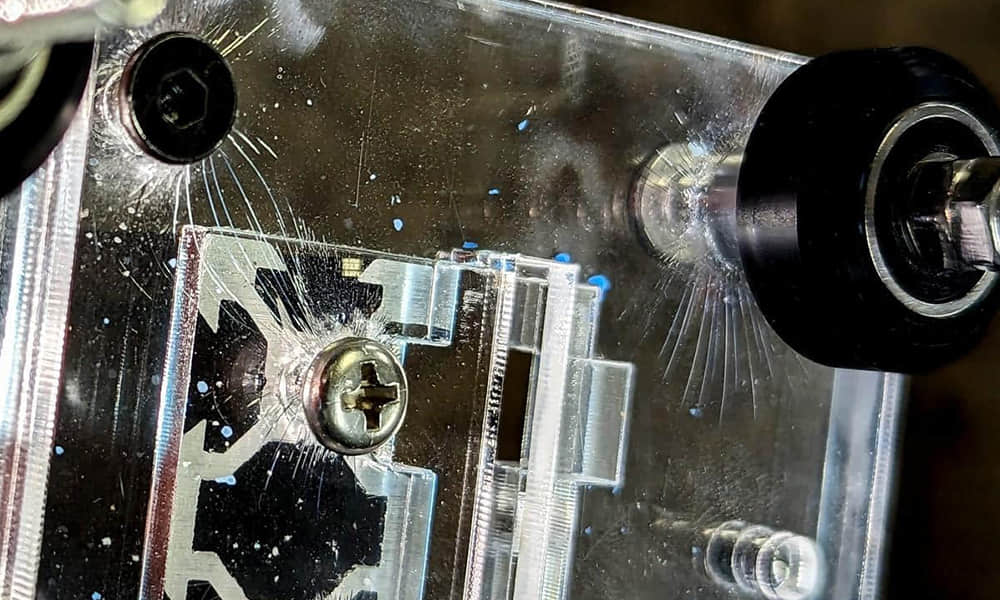
Screw tightening is one of the first items to check when cracks begin around mounting holes. A plastic optical lens should not be treated like a metal plate. Excessive or uneven tightening can bend the component and concentrate tensile stress around the hole.
Common fastening problems include:
- Torque exceeding the structure’s validated limit;
- Tightening one screw completely before positioning the others;
- Using unsuitable screw heads or washers;
- Misaligned housing bosses and lens holes;
- Fasteners pulling the lens onto a distorted housing;
- Thread-locking chemicals contacting the optical material.
Fastening-related cracks often radiate outward from a screw hole or begin where the screw head contacts the lens.
How to Verify a Fastening Problem
- Assemble samples at several controlled torque levels.
- Record the tightening sequence and tool used.
- Compare assemblies with and without the gasket.
- Inspect immediately after assembly and after temperature testing.
- Measure housing flatness and mounting-boss height.
There is no universal screw torque for all optical lenses. The acceptable value depends on material grade, lens thickness, screw head, washer, gasket and housing structure.
2. Excessive or Uneven Gasket Compression
A gasket supports enclosure sealing but also applies force to the lens. Excessive or uneven compression can bend the lens or push it against the housing.
Possible causes include:
- Gasket thickness exceeding the designed sealing gap;
- Different mounting-boss heights;
- A twisted or displaced gasket;
- Gasket hardness that is unsuitable for the structure;
- Uneven screw tightening;
- Housing deformation during assembly;
- Incompatible chemicals migrating from the gasket.
The highest gasket compression does not automatically provide the most reliable seal. The complete luminaire should be tested for both ingress protection and mechanical stress.
3. Housing, PCB or Locating-Feature Interference
A lens may fit the nominal CAD model but experience interference when real production tolerances are included. If the housing, PCB and lens dimensions move in unfavorable directions, assembly can force the optical component into a permanently stressed condition.
Typical interference points include:
- Locating pins that are too large or too far apart;
- PCB edges contacting the lens support structure;
- Housing ribs pressing against the lens perimeter;
- Mounting holes that do not align with the bosses;
- Insufficient expansion clearance around a large array;
- Warped PCBs or die-cast housings;
- LED packages contacting the optical cavities.
Large arrays are particularly sensitive to accumulated dimensional differences. A small pitch error repeated across several LEDs may create significant interference at the far end of the component.
Asahi’s guide on matching an LED lens to a PCB layout explains why LED pitch, optical-center alignment, PCB dimensions and LED-to-lens distance should be reviewed as one system.
How to Check Structural Interference
- Measure actual production parts instead of relying only on nominal drawings.
- Review maximum and minimum tolerance combinations.
- Place the lens in the housing without screws and check whether it sits flat.
- Inspect whether the lens springs upward after the fasteners are removed.
- Compare failed and acceptable housings for flatness and boss height.
If the lens must be forced into position before fastening, the mechanical interface should be corrected before mass production continues.
4. Injection-Molding Residual Stress
Transparent optical components can contain internal stress even when no visible damage is present. During injection molding, molten polymer flows through the cavity, cools and contracts. Differences in molecular orientation, wall thickness, pressure and cooling rate can leave stress locked inside the finished part.
Research into injection-molded polycarbonate optics indicates that excessive packing pressure and unsuitable cooling conditions can increase residual stress and contribute to cracking, warpage and dimensional instability. See this study on injection-molding conditions for polycarbonate optical lenses.
Important process variables include:
- Resin drying condition;
- Melt and mold temperature;
- Injection speed;
- Packing pressure and time;
- Gate size and position;
- Cooling balance;
- Wall-thickness transitions;
- Demolding force and timing.
A high packing pressure may reduce sink marks while increasing stress in another region. A low mold temperature can solidify the outer surface quickly while the core continues to shrink.
Signs of a Molding-Related Problem
- The crack repeats at the same position in one mold cavity.
- Different assembly stations show the same failure pattern.
- Unassembled samples fail during thermal testing.
- Polarized-light inspection shows strong stress near the crack origin.
- The failure rate changes after adjusting the molding process.
- Parts also show warpage, sink marks or difficult demolding.
If the failure follows a mold cavity instead of an assembly station, review the mold and process before changing the luminaire structure. Asahi’s optical lens mold development combines optical geometry, mold structure, material flow and production verification.
5. Chemical Stress Cracking
Chemical stress cracking occurs when a chemical and tensile stress act together on a polymer. The chemical may not visibly dissolve the material. Instead, it reduces the material’s resistance until fine crazing or a deeper crack forms.
This explains why a cleaner can appear harmless on a loose sample but damage the same material after it has been fastened into a housing.
Potential chemical sources include:
- Alcohol-based cleaners;
- Acetone and strong solvents;
- Ammonia-based cleaning products;
- Thread-locking compounds;
- Adhesives and primers;
- Sealants and curing agents;
- Lubricants and cutting fluids;
- Plasticizers migrating from cables or nearby plastics;
- Foam, rubber and packaging materials;
- Industrial vapors and airborne contaminants.
Chemical compatibility depends on material grade, stress, concentration, exposure time and temperature. Covestro’s guidance on polycarbonate chemical resistance notes that tensile stress is required for stress cracking and that the time before damage varies with chemical and operating conditions.
Can Alcohol Damage an LED Optical Lens?
Do not assume that every PC or PMMA component can be cleaned with alcohol. Compatibility varies by resin grade, alcohol formulation, concentration, exposure time and molded-in stress.
Asahi product handling instructions generally recommend mild soap, water and a soft cloth and advise against commercial cleaning solvents. If cleaning is part of the customer’s production process, test the exact cleaner on the actual molded and assembled component.
A raw-material coupon cannot reproduce all production conditions, including screw load, gasket pressure, operating temperature and molded-in stress.
How to Investigate Chemical Crazing
- Record every chemical used during molding, assembly, cleaning and packaging.
- Include vapors, sprays, wipes, grease, adhesives and thread lockers.
- Compare cleaned and uncleaned assembled samples.
- Test the chemical at its intended concentration and temperature.
- Inspect high-stress areas around screws, clips and gasket edges.
6. LED Heat and Thermal Cycling
The temperature near an LED board can be substantially higher than ambient temperature. Thermal conditions affect the lens because the optical material, PCB and housing expand at different rates.
Repeated heating and cooling can add stress to constrained regions. Elevated temperature may also accelerate chemical reactions and reduce the time required for crazing to appear.
Measure representative points on the complete luminaire:
- LED board near the highest-power LEDs;
- Optical surface directly above the LEDs;
- Mounting holes and gasket interface;
- Internal air near the optical component;
- Housing around the mounting structure.
Testing should use the intended LED current, driver, housing, thermal interface and installation orientation. An open laboratory setup may not reproduce the temperature inside a sealed production luminaire.
Signs of a Thermal Problem
- Cracks appear only after the luminaire operates.
- The failure rate increases at higher ambient temperatures.
- Damage begins near a high-power LED or local hot area.
- Unpowered assembled samples do not fail.
- Changing the LED current or heatsink changes the result.
- Cracks become visible after thermal cycling.
7. Handling, Impact and Packaging Damage
Some cracks begin before assembly. Optical components can be damaged by dropped trays, excessive stacking pressure, sharp packaging edges or contact with tools.
A small edge notch created during transport may later become the origin of a larger crack after fastening or thermal cycling.
Preventive measures include:
- Separating optical surfaces and sharp edges in the packaging;
- Avoiding excessive stacking pressure;
- Using clean gloves during handling;
- Keeping metal tools away from optical surfaces;
- Protecting locating pins and thin perimeter features;
- Inspecting dropped parts before returning them to production.
PMMA vs PC: Different Cracking Risks
PC and PMMA are widely used for lighting optics, but neither is suitable for every environment. For a complete material comparison, see What Are LED Lenses Made Of?.
| Evaluation factor | PMMA | PC |
|---|---|---|
| General mechanical behavior | Rigid with high optical clarity, but comparatively brittle | Tough with higher impact resistance |
| Typical cracking concern | Fracture from impact, bending or concentrated assembly load | Environmental stress cracking under load and chemical exposure |
| Temperature consideration | Requires careful verification near high-power LEDs | Often considered for higher-temperature applications, depending on grade |
| Mounting consideration | Avoid forced assembly and sharp stress concentration | Avoid continuous tensile strain and incompatible chemicals |
| Final decision | Test the exact resin grade, molded geometry and complete luminaire | |
High impact resistance cannot compensate for an incorrect assembly structure, while high optical transmission cannot compensate for an unsuitable operating temperature.
What the Crack Location Can Tell You
| Crack location or pattern | Priority causes | Recommended verification |
|---|---|---|
| Radial crack around a screw hole | Excessive torque, hole misalignment or unsuitable screw head | Controlled torque test and housing measurement |
| Crack between mounting holes | Lens bending, uneven bosses or gasket compression | Assemble without the gasket and check contact pressure |
| Crack at a locating pin | Interference fit or positional tolerance | Measure pin and hole dimensions |
| Fine white lines near a fastener | Chemical exposure combined with tensile stress | Compare cleaned and uncleaned assemblies |
| Crack above an LED | Local heat, LED contact or insufficient clearance | Temperature mapping and clearance inspection |
| Same crack from one mold cavity | Gate, cooling, demolding or residual stress | Cavity traceability and polarized-light inspection |
| Random cracks after thermal cycling | Combined molding, assembly and thermal stress | Compare loose, assembled and powered samples |
| Surface network after cleaning | Environmental stress cracking | Chemical-elimination test on assembled parts |
The crack pattern helps prioritize the investigation, but it does not independently prove the root cause.
A Practical LED Lens Failure Investigation
1. Preserve Traceability
Quarantine affected parts and record the material batch, molding date, mold cavity, assembly station and test history.
2. Record When the Failure Appeared
Determine whether the damage appeared after molding, transport, fastening, cleaning, sealing, powered operation or environmental testing.
3. Photograph the Crack Before Disassembly
Take front, rear and side photographs under diffuse and directional light. Record whether the crack aligns with a screw, pin, gasket, LED, gate or weld line.
4. Compare Controlled Sample Groups
- Loose molded component;
- Component placed in the housing without screws;
- Assembly without gasket;
- Assembly with gasket;
- Different controlled torque levels;
- Cleaned and uncleaned assemblies;
- Powered and unpowered assemblies.
Change one factor at a time. Multiple simultaneous changes make the result difficult to interpret.
5. Inspect Residual Stress
Polarized-light inspection can reveal comparative stress patterns around mounting holes, gates and thickness transitions. It should be used together with process and mechanical data.
6. Check Dimensions and Chemicals
Measure actual lens, PCB, gasket and housing dimensions. Record the exact commercial name, supplier and concentration of every cleaner, adhesive, sealant and lubricant.
7. Reproduce and Verify the Corrective Action
A proposed correction should eliminate the failure under the condition that originally produced it. If the torque is reduced or a cleaner is replaced, repeat the relevant mechanical, thermal and environmental tests.
How to Prevent Cracking During Luminaire Development
- Provide mechanical clearance: allow for manufacturing tolerance and thermal expansion.
- Avoid sharp stress concentration: review thin sections, mounting holes and abrupt geometry changes.
- Control fastening: define the screw, washer, sequence, torque tool and inspection method.
- Validate gasket compression: check sealing pressure, hardness and chemical compatibility.
- Select the correct material grade: consider temperature, impact, UV and chemical exposure.
- Approve production chemicals: test cleaners, adhesives and sealants on stressed assemblies.
- Maintain traceability: record resin batch, mold cavity and assembly station.
- Test the complete luminaire: include the actual LED, PCB, housing, gasket and fasteners.
Information to Send for a Technical Review
| Required information | Why it matters |
|---|---|
| Lens model and material grade | Identifies geometry and resin characteristics |
| Material batch and mold cavity | Supports molding traceability |
| Photographs before and after assembly | Shows crack origin and failure stage |
| PCB and housing drawings | Allows tolerance and interference review |
| Screw type, torque and sequence | Defines assembly load |
| Gasket drawing and material | Supports compression and compatibility analysis |
| LED model and operating current | Supports clearance and thermal analysis |
| Measured component temperature | Shows the actual operating condition |
| Cleaner, adhesive and sealant details | Supports chemical compatibility review |
| Failure timing and failure rate | Helps separate molding, assembly and service causes |
When possible, provide failed parts and acceptable comparison samples. A loose component, an assembled failed luminaire and an acceptable assembly can provide more evidence than photographs alone.
When Is a New Optical Structure Required?
A process adjustment may solve the problem if the existing design has sufficient mechanical and thermal margin. A structural change should be considered when:
- The lens must be forced into the housing;
- Mounting holes cannot align across production tolerances;
- The gasket requires excessive deformation to seal;
- Cracks repeatedly begin at an unavoidable geometry transition;
- The material cannot tolerate the operating temperature or chemicals;
- The optical cells contact the LED package;
- The housing does not provide thermal-expansion clearance.
If an existing product cannot meet both the optical and mechanical requirements, Asahi’s custom optical development service can evaluate the LED, PCB, lens structure, mold, sealing interface and operating environment as one system.
Conclusion: Identify the Stress Combination
LED lens cracking is usually the visible result of an interaction among material, injection molding, assembly force, chemicals and temperature.
A radial fracture around a screw hole points toward fastening or alignment stress. Fine white crazing after cleaning suggests chemical stress cracking. Repeated damage from one mold cavity may indicate residual stress, while cracks appearing only after powered thermal cycling require combined mechanical and thermal investigation.
The most reliable corrective action comes from controlled comparison:
- Loose versus assembled component;
- Low versus high fastening load;
- Cleaned versus uncleaned sample;
- Powered versus unpowered assembly;
- Different mold cavities and material batches;
- Original versus revised housing or gasket.
If an optical component cracks during assembly, cleaning or luminaire testing, contact Asahi Optics for a technical review. Send the failure photographs, LED and PCB information, housing drawing, fastening method, operating temperature and chemical details so the likely cause can be evaluated efficiently.