Choose an LED emergency light lens around the actual emergency-mode output, mounting geometry and required floor-level illumination. A bright patch beneath a fitting does not show whether the route between fittings is adequately lit. The useful question is where the available light reaches the floor, especially at the weakest points.
For luminaire manufacturers and OEM engineering teams, this means selecting the distribution and installation arrangement together. This guide focuses on building escape-route lighting, rather than illuminated exit signs, portable lamps or emergency vehicle warning lights.
Start with Emergency Output and Escape Route Requirements
Establish the emergency operating condition before comparing optics. LED source lumens, complete-luminaire lumens and emergency-mode lumens are different inputs. Where a fitting operates at reduced output during a power failure, its normal-mode rating cannot be used directly to determine emergency lighting spacing.
Prepare the following design inputs:
- Emergency operation: LED model, emergency driver configuration, available luminous output and rated duration.
- Route geometry: mounting height above the relevant floor or stair surface, route width, proposed fitting positions and changes in direction.
- Installation constraints: ceiling-centred or offset mounting, obstructions, available optical space and protective covers.
- Project requirements: applicable standards, assessment areas, illuminance limits, uniformity and glare criteria.
Confirm the region and applicable edition rather than combining requirements from different jurisdictions. For example, BSI's overview of BS EN 1838:2024 describes revised requirements addressing the width of escape routes and routes passing through open areas. Checking only a centreline is therefore not a sufficient description of the assessment. The exact calculation boundaries and requirements should come from the standard applicable to the project.
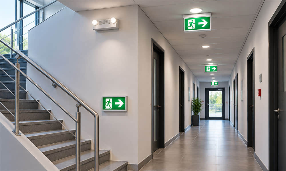
Also distinguish route illumination from exit-sign visibility. An illuminated sign identifies the way out; its presence alone does not establish adequate illumination of the walking surface.
Choose a Distribution That Fits the Route
Match the direction of light distribution to the route's shape and the fitting's position. A nominal beam angle by itself says too little about where the useful light falls.
| Installation condition | Distribution feature to examine | Main selection risk |
|---|---|---|
| Straight, narrow corridor | Intensity along the route, with sufficient transverse spread across the assessment area | A bright centre strip with weak edges, or dark gaps between fittings |
| Route entering an open area or junction | Continuity between the route and the adjoining area, including changes in travel direction | Extending one corridor distribution into an area it does not adequately illuminate |
| Higher mounting position | Intensity reaching the required floor positions at the actual distance and angles | Assuming a larger footprint automatically permits greater spacing |
For corridor emergency lighting, an elongated distribution can place more light along the walking direction than a circular spotlight. Its transverse distribution still matters: increasing longitudinal reach is not useful if the required route width remains too dark.
An elongated beam is not automatically an asymmetric beam. A ceiling-centred fitting may distribute light symmetrically in both directions along a corridor. An offset or wall-mounted fitting may need a different distribution to put light onto the same route. Select from the measured intensity pattern and installation geometry, not from the word “oval” or “asymmetric” alone.
At turns, stairs and junctions, first reconsider fitting position and orientation. A local change in layout may address the problem more directly than replacing every optic with a wider distribution.
Match the Lens to the Actual LED and Luminaire
A promising distribution is only relevant if the lens receives light from the source position for which it was designed. Check optical compatibility before committing the PCB or housing to production.
Use the Exact LED Model, Not Just the Package Size
Package labels such as 3535 do not fully describe the light-emitting surface, dome or source geometry. A lens characterised with one LED should not be assumed to produce the same distribution with another LED simply because both fit the same footprint. Ask which LED model and operating conditions were used for the supplied photometric data.
Control Alignment, Height and Orientation
Confirm the optical centre, LED-to-lens distance and locating features. For a directional corridor optic, the assembly also needs a clear orientation reference. A fitting that can be assembled in the wrong rotational position can send its longer distribution across the corridor instead of along it.
Define these relationships on the drawing rather than relying on visual placement. Our guide to matching an LED lens to a PCB layout explains the mechanical and optical checks in more detail.
Check the Complete Optical Opening
Housing edges, holders and protective covers can intercept or redirect light. This is particularly important when the intended distribution relies on light leaving the fitting at relatively large angles. Verify the assembled luminaire, not only the exposed LED-and-lens combination.
Verify Luminaire Spacing with Emergency-Mode Photometry
Determine spacing from calculated floor illuminance using representative emergency-mode photometric data. Do not infer a maximum distance between LED emergency lights from lens diameter, LED wattage or a single beam-angle figure.
- Confirm what the file represents. Identify the complete luminaire, LED, optic, cover, drive condition and output basis associated with the IES or LDT file. Prefer supplier-issued data for the intended emergency configuration.
- Set the actual installation geometry. Enter mounting positions, height, orientation, route boundaries and relevant obstructions. Model stairs and other changes in level separately where necessary.
- Examine the weakest positions. Review a suitable calculation grid across the required assessment area, including gaps between fittings, route edges and transitions. Check minimum illuminance and the specified uniformity measure, not only average illuminance.
- Check the wider performance requirements. Assess applicable glare criteria and confirm that the output assumptions represent the required emergency operating period and maintenance condition.
If normal-mode photometry is used as a starting point, obtain the manufacturer's confirmation that its distribution and the proposed luminous-output scaling remain valid for the exact emergency configuration. Do not substitute the ratio of electrical wattages. Avoid applying a second emergency reduction if the file already includes emergency-mode output, and document any maintenance factors separately.
A beam angle defined by full width at half maximum, or FWHM, identifies directions where intensity falls to half its peak. It does not define the floor area that meets a specified illuminance. A calculated FWHM footprint is therefore not a substitute for a spacing assessment.
When comparing candidate emergency lighting optics, keep the LED, emergency output, mounting height and layout consistent. Compare the minimum floor illuminance, transverse distribution, uniformity and relevant glare results. A higher peak directly below the fitting is not a sufficient reason to select one lens over another.
Optical performance is also only one part of product approval. IEC 60598-2-22:2021 addresses emergency luminaires and includes requirements involving batteries, high-temperature operation and other safety considerations. Selecting a lens does not establish compliance of the complete luminaire or its installation.
Troubleshoot Dark Zones Before Increasing Power
Identify whether the shortfall comes from distribution, positioning, assembly or available output before changing the power level. Use controlled engineering samples for component removal or rotation tests; do not make unapproved changes to an installed emergency lighting system.
| Observed problem | What to check first | Possible next action |
|---|---|---|
| Dark gap between fittings | Compare measured and calculated illuminance in the gap; verify emergency output, spacing and intensity in the directions feeding that position. | Evaluate a distribution with more useful longitudinal intensity, reduce spacing or revise fitting positions. |
| Acceptable centre readings but weak route edges | Measure across the assessment width and check whether the fitting is offset from its intended position. | Evaluate more suitable transverse spread or change the mounting arrangement. |
| The longer beam runs across the corridor | Compare lens markings, PCB references and the installed fitting direction with the optical drawing. | Correct orientation and introduce a positive locating feature or clearer assembly marking. |
| The distribution changes after the housing or cover is fitted | Compare the prototype with and without the relevant component under matched drive and thermal conditions. | Investigate clipping, cover effects or displacement of the optical assembly, then retest the complete fitting. |
If the measurements disagree with the calculation across the whole route, check the test setup before redesigning the optic. Incorrect file scaling, mounting orientation, output assumptions or ambient light can make a sound design appear to fail. Our guide to testing LED lens optical performance covers repeatable sample evaluation.
Increasing output is a system decision, not an optical adjustment alone. If more output is required, reassess the driver, battery, thermal conditions and rated duration rather than assuming the existing electrical configuration can support the change.
Prepare the Information Needed for Lens Matching
A useful lens enquiry starts with the route and emergency operating condition, not just a requested beam angle. To begin an optical review with Asahi Optics, send:
- The LED model and available emergency-mode output or driver information.
- Mounting height, route width, proposed spacing and the applicable lighting requirements.
- The available lens space and relevant PCB or housing drawing.
If available, include the existing IES/LDT file, a layout and measured dark-zone readings. These help distinguish a distribution issue from an assembly or positioning problem.
Send your emergency lighting requirements to Asahi Optics. Our initial review can identify candidate existing optics, highlight LED or mounting compatibility obstacles, and explain what additional data is needed for selection. Where an existing option is unsuitable, a custom optical design can be considered against the same project requirements.