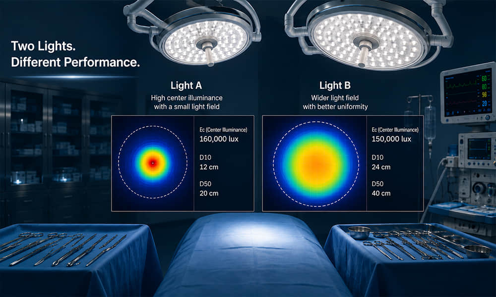
Two surgical lights may report similar maximum illuminance but perform very differently in an operating room. One may produce a small, highly concentrated center, while another maintains useful illumination across a wider field. Their performance may also change differently when a surgeon’s head, hands or instruments obstruct part of the light.
To make a meaningful comparison, buyers and luminaire engineers must look beyond the highest lux value. Surgical light specifications such as central illuminance Ec, D10, D50, illumination depth and shadow dilution describe different aspects of the complete light field.
This guide explains how to read these values, identify incompatible test conditions and determine what optical information is needed when selecting a surgical light lens.
Why Maximum Lux Does Not Tell the Whole Story
Maximum lux is often the most prominent number on a surgical light datasheet. It is easy to understand and convenient for product comparison, but it only describes illuminance at a defined position.
It does not independently tell you:
- How large the illuminated field is
- How quickly illuminance falls from the center toward the edge
- How far useful illumination extends along the optical axis
- How the light behaves when part of the lamp head is obstructed
- Whether the light field contains rings, hot spots or color variation
- Whether the measurement was taken in a normal or temporary boost mode
A value such as 140,000 or 160,000 lux therefore cannot be evaluated without its test conditions. At minimum, check the reference distance, operating mode, selected color temperature, light-field setting and measurement tolerance.
It is also important to use the correct photometric terminology. Lux measures illuminance on a surface, while candela describes luminous intensity in a direction. These quantities are related but not interchangeable. Our guide to lumen, lux, luminous intensity and luminance explains the distinction in detail.
Key Surgical Light Datasheet Terms at a Glance
| Parameter | What It Describes | What to Check |
|---|---|---|
| Central illuminance, Ec | Illuminance at the center of the light field | Reference distance, operating mode, CCT and tolerance |
| D10 | Diameter of the field where illuminance reaches 10% of Ec | Measurement plane and field setting |
| D50 | Diameter of the field where illuminance reaches 50% of Ec | D50 value together with D10 |
| D50/D10 | Relative size of the half-illuminance core within the overall field | Values calculated under the same condition |
| Illumination depth | Axial distance over which a defined percentage of Ec is maintained | Whether the threshold is based on 20%, 60% or another definition |
| Shadow dilution | Remaining illumination when parts of the light path are obstructed | Mask, tube, position and calculation method |
| Ee | Irradiance reaching the illuminated surface | Test mode, distance and units |
| Ee/Ec | Radiant energy in relation to illuminance | Exact units and test conditions |
What Is Central Illuminance Ec?
Central illuminance Ec is the illuminance measured at the center of the surgical light field under a defined test condition. Its unit is lux.
Ec is commonly used to describe the maximum or reference output of an operating room light. However, the measurement is meaningful only when the position of the luminaire and measurement plane is stated.
Ec Is Illuminance, Not Luminous Intensity
Central illuminance is sometimes incorrectly called “light intensity.” In photometric terminology, illuminance and luminous intensity are different quantities:
- Illuminance: the amount of light arriving on a surface, measured in lux
- Luminous intensity: the amount of light emitted in a particular direction, measured in candela
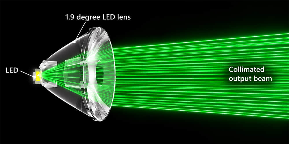
A narrow-beam lens can increase candela in the central direction and may consequently increase lux at the target plane. However, the resulting Ec still depends on LED output, optical efficiency, working distance, lens distribution and the number of active optical channels.
Why Reference Distance Matters
Illuminance changes with distance. If two datasheets use different measurement distances, their central lux values cannot be compared directly.
Moving the measuring plane also changes the diameter and overlap of the individual beams. In a multi-lens surgical luminaire, the beams may be designed to converge within a particular working range. Measuring before, at or beyond this region can produce different Ec, D10 and D50 results.
When reading an operating room light specification, confirm:
- The reference distance from the light-emitting surface to the measuring plane
- Whether Ec is measured at the reference distance or at the point of maximum illuminance
- Whether automatic distance compensation was active
- The selected light-field diameter
- The dimming or boost setting
How to Compare Ec Values Correctly
Suppose Luminaire A reports 160,000 lux and Luminaire B reports 140,000 lux. It would be incorrect to conclude immediately that Luminaire A provides the better surgical field.
Luminaire A may have been measured in boost mode with a small field, while Luminaire B may maintain 140,000 lux across a larger field in its normal operating mode. Luminaire B might also retain more illumination when the lamp is partially obstructed.
A reliable comparison should place Ec beside D10, D50, illumination depth and shadow-dilution results. The test report should identify the standard edition and measurement conditions. The current IEC 60601-2-41:2021 addresses the basic safety and essential performance of surgical luminaires and luminaires for diagnosis. It does not apply to every type of medical light, including dental luminaires and surgical headlights.
What Do D10 and D50 Mean?
D10 and D50 describe the diameter of the illuminated field at two percentages of central illuminance. They help show whether the luminaire produces a broad usable field or a narrow central peak surrounded by a weaker outer area.
D10: The Outer Light Field
D10 is the diameter of the area where illuminance reaches 10% of Ec. It represents the broader boundary of the measured light field.
A large D10 may indicate wide coverage, but it does not necessarily mean that the entire area has strong or uniform illumination. Much of the outer field may be considerably weaker than the center.
D50: The Half-Illuminance Field
D50 is the diameter of the area where illuminance reaches 50% of Ec. It describes the more concentrated central portion of the light field.
D50 is particularly useful because it shows how much of the field retains at least half of the central illuminance. A datasheet that provides only its widest field diameter does not give enough information to evaluate the effective central region.
Why D10 and D50 Must Be Read Together
Consider two hypothetical surgical lights:
- Luminaire A: D10 = 25cm and D50 = 15cm
- Luminaire B: D10 = 25cm and D50 = 10cm
Both products have the same D10, but their central fields are different. Luminaire A maintains 50% of Ec across a larger portion of the total field, while Luminaire B has a smaller half-illuminance core and a steeper decline toward the edge.
This example does not prove that Luminaire A is suitable for every procedure. It demonstrates why D10 alone is insufficient.
How to Interpret the D50-to-D10 Relationship
The D50/D10 relationship describes the size of the half-illuminance region relative to the overall field. Using the hypothetical values above:
- Luminaire A: 15 ÷ 25 = 0.60
- Luminaire B: 10 ÷ 25 = 0.40
A larger ratio generally indicates a broader half-illuminance core relative to the outer field. However, the ratio should not be treated as a complete uniformity score. It does not show local hot spots, rings, asymmetry or irregular contours inside the measured field.
Ask for an illuminance map, polar distribution or complete photometric test result if field quality is critical. D10, D50 and their ratio should always be compared at the same distance, field setting, CCT and output mode.
What Is Surgical Light Illumination Depth?
Surgical light illumination depth describes the axial range over which the light maintains a defined proportion of its central illuminance. It helps indicate how the light performs when the target is located above or below the nominal reference plane.
This parameter is relevant to procedures requiring useful light within a cavity rather than only on a flat surface. However, the word “depth” can be misleading unless its threshold and measurement method are specified.
Check the Percentage Threshold
Some datasheets report the distance over which illuminance remains at or above 60% of Ec. Others provide a result based on 20% of Ec. Because a beam remains above a lower threshold for a longer distance, the 20% value will normally be greater than the 60% value.
Therefore, these statements cannot be compared directly:
- Illumination depth: 120cm at 20% Ec
- Illumination depth: 65cm at 60% Ec
The first number is larger, but it uses a much lower illuminance threshold. The datasheet should state the threshold, reference Ec, measurement direction and operating configuration.
Why a Narrow Beam Does Not Automatically Mean Greater Depth
A narrow nominal beam can help concentrate light, but beam angle alone does not determine illumination depth. The final result also depends on:
- LED emitting-surface dimensions
- Lens-to-LED position
- Lamp-head diameter
- Orientation of individual lenses
- Convergence distance of the optical channels
- Number and distribution of LEDs
- Protective cover and other optical surfaces
If the beams converge too sharply at one plane, the system may create a strong illuminance peak but lose useful coverage before and after that position. Surgical luminaire development must therefore evaluate a three-dimensional illumination volume rather than only a flat wall spot.
What Is Shadow Dilution?
“Shadowless surgical light” is a common commercial term, but a luminaire cannot completely eliminate shadows. Instead, ceiling-mounted surgical lights use multiple beams arriving from different directions to reduce the contrast of shadows caused by a surgeon, instrument or other obstruction.
This process is more accurately described as shadow dilution. When one section of the lamp head is blocked, the remaining optical channels continue to illuminate the operating field.
Our separate guide explains in more detail how lenses and multi-directional light create the shadowless effect. When reading a datasheet, the immediate concern is how the test was performed.
Common Obstruction Test Conditions
Shadow-dilution data may be reported under several configurations:
- One mask obstructing part of the light head
- Two masks obstructing different light paths
- A tube used to represent a deep cavity
- One mask combined with a tube
- Two masks combined with a tube
The reported percentage normally represents remaining illumination relative to an unobstructed condition, but the datasheet or test report should confirm the calculation. A higher remaining-illumination percentage generally indicates that the system retains more light under that particular obstruction condition.
Do not compare one-mask data from one product with two-mask-and-tube data from another. The number and position of the obstructions, tube dimensions, working distance, field setting and calculation method must be equivalent.
What Affects Shadow-Dilution Performance?
Shadow dilution is a system-level result influenced by:
- Lamp-head diameter and shape
- Number of independently positioned light sources
- Angular separation between optical channels
- Individual lens distributions
- Beam-overlap accuracy
- Size and uniformity of the final light field
A single lens cannot create the complete effect. The function of the lens is to produce a predictable beam that can be aimed and combined with the other channels.
How Should CRI, R9 and CCT Be Compared?
Color parameters matter in surgical lighting because clinicians must distinguish subtle differences among tissues, vessels and fluids. Nevertheless, this article does not need to repeat the complete definitions of CRI or color temperature.
When comparing a surgical light datasheet, remember:
- General CRI or Ra is usually derived from test-color samples R1 to R8.
- R9 evaluates saturated red and should be checked separately rather than assumed from Ra.
- CCT describes the visual color of the emitted white light; it does not describe color-rendering quality.
- A tunable-white surgical light should be evaluated at each selectable CCT.
- Changing CCT may also change Ec, Ra, R9 or the balance among optical channels.
More detailed explanations are available in our guides to CRI and R9 and correlated color temperature.
These values are primarily determined by the LED spectrum and complete luminaire. A lens should transmit the required visible spectrum without unacceptable color shift, but it should not be described as a “high-CRI lens.” The complete LED, lens, cover and control configuration must be measured together.
Radiant Energy and Thermal Information
High illuminance should also be considered together with the radiant energy delivered to the illuminated area. Datasheets may provide total irradiance Ee and a ratio relating irradiance to central illuminance.
Before comparing these values, check the units carefully. Manufacturers may present irradiance in W/m² and energy-to-illuminance ratios using different unit scales. A numerical comparison is unreliable if one datasheet uses lux while another expresses the denominator in kilolux.
It is equally important to separate radiant energy at the surgical field from heat inside the lamp head. LED junction temperature, PCB temperature, driver losses and lens operating temperature are different engineering issues.
An efficient optical lens can direct more useful light toward the target and reduce wasted output. However, the lens cannot replace proper heatsink design, LED current control or full-luminaire thermal testing.
How to Compare Two Surgical Light Datasheets
The following checklist can be used during technical evaluation or supplier qualification.
| Item to Compare | What to Verify | Common Mistake |
|---|---|---|
| Central illuminance | Distance, mode, field size, CCT and tolerance | Selecting the product with the highest lux value |
| D10 and D50 | Both diameters under the same test condition | Comparing only the widest field diameter |
| D50/D10 | Ratio and supporting illuminance distribution | Treating the ratio as a complete uniformity measurement |
| Illumination depth | Percentage threshold, direction and reference Ec | Comparing a 20% result with a 60% result |
| Shadow dilution | Mask quantity, tube, position and calculation | Comparing results from different obstruction configurations |
| CRI and R9 | Results at each selectable CCT | Assuming high Ra guarantees strong red rendering |
| Radiant energy | Ee, Ee/Ec, test distance and units | Comparing numbers expressed with different unit scales |
| Testing standard | Edition, laboratory, report and product configuration | Accepting “IEC compliant” without supporting conditions |
| Measurement tolerance | Tolerance for each optical value | Treating nominal figures as exact production results |
Check Whether the Values Come from the Same Configuration
A surgical light may have several output levels, CCT settings and adjustable field diameters. The highest Ec may be measured using a different configuration from the largest D10 or best shadow-dilution result.
Ask whether all headline specifications can be achieved simultaneously. If not, the datasheet should make the configuration for each result clear.
Request Measured Data, Not Only Marketing Descriptions
Terms such as “deep-cavity lighting,” “perfect uniformity” and “excellent shadowless performance” are not substitutes for measured results.
Useful supporting information includes:
- Complete photometric report
- Illuminance distribution map
- D10 and D50 measurement results
- Axial illumination curve
- Shadow-dilution test configuration
- Spectral and color-rendering measurements
- Measurement tolerance
How LED Lenses Affect Surgical Light Specifications
The optical lens sits between the LED and the final surgical field. It collects and redirects light so that each LED produces a controlled contribution to the complete beam.
Well-matched surgical lighting optics can influence:
- Central beam concentration and Ec
- The size and shape of D10 and D50
- Field-edge transition
- Beam overlap and visual uniformity
- Axial illuminance distribution
- Light remaining after part of the lamp head is obstructed
- Stray light, rings and secondary hot spots
However, the lens does not independently determine the luminaire’s medical certification, CRI, R9, CCT, electrical safety or thermal performance. These are properties of the complete product.
Our Surgical Lighting Optics application page explains how narrow-beam lenses, multi-source layouts and working-distance requirements are combined during operating room light development.
Why the LED Model Must Be Confirmed
The same lens can produce different beams with different LEDs. Package dimensions alone are insufficient because two nominally similar LEDs may have different light-emitting surfaces, dome structures and radiation patterns.
The LED-to-lens distance also affects the result. A small positioning error may change beam width, central intensity or field uniformity, especially when the luminaire uses very narrow optical distributions.
Why a Single-Lens Test Is Not Enough
Testing one lens is useful for checking basic compatibility and distribution. It does not prove that the complete lamp head will achieve the required D10, D50, illumination depth or shadow dilution.
The full system must account for:
- LED quantity and PCB positions
- Lens orientation and tilt angle
- Mechanical assembly tolerance
- Protective cover transmission
- Interaction among overlapping beams
- Operating temperature and LED output
A fixture prototype should therefore be measured after the intended LEDs, lenses, holders, PCB and protective cover have been assembled.
What Information Should You Provide for Surgical Light Lens Selection?
Asahi’s Surgical Lighting Single Lens range includes several lens diameters and narrow-beam options. To recommend an existing lens, we need more than a requested beam angle.
Please provide:
- LED manufacturer and complete part number
- LED package drawing and light-emitting-surface dimensions
- LED ray file or radiation data, if available
- Required working distance
- Target central illuminance Ec
- Required D10 and D50
- Illumination-depth target and percentage threshold
- Lamp-head diameter and shape
- Number and arrangement of LEDs
- PCB drawing and available lens space
- Permitted lens orientation or tilt
- Protective cover material and position
- Prototype acceptance and test criteria
These inputs allow us to compare the required optical field with existing lens distributions. If a standard lens is close to the target, samples can be evaluated with the customer’s LED and fixture geometry.
When an existing optic cannot satisfy the LED, working distance, field diameter or mechanical envelope, Asahi can provide optical design and lens development. Any dedicated design should still be validated through simulation, prototype measurement and complete-luminaire testing.
Compare the Complete Light Field, Not One Number
A surgical light datasheet should be read as a connected set of measurements. Ec describes central illuminance. D10 and D50 describe the size and shape of the field. Illumination depth describes axial performance, while shadow dilution shows how the system behaves when light paths are obstructed.
CRI, R9, CCT, radiant energy and thermal data add further information, but none of these values should be separated from its test condition. The most reliable comparison uses the same reference distance, operating mode, field setting, measurement threshold and standard edition.
If you are developing an operating room light, send Asahi Optics your LED model, working distance, target Ec, D10 and D50, illumination-depth requirement, lamp-head structure and PCB drawing. We can review available optics and help identify suitable samples for your prototype.