When comparing LED spotlights vs halogen, the most useful question is whether the LED delivers the required light on the object—not whether the packaging shows a similar wattage or beam angle. A successful replacement preserves the intended illumination, beam transition and visual emphasis while keeping unwanted light under control.
For luminaire manufacturers and commercial lighting teams, this means comparing the complete lighting effect. A brighter center is not necessarily an improvement if the display edges become dark, the surrounding wall becomes too bright or the merchandise looks different.
Define the Halogen Lighting Effect You Want to Keep
Start with the installation rather than the replacement lamp. Record the target dimensions, distance from the spotlight to the target, aiming direction and normal viewing positions.
Then identify what makes the existing effect useful:
- Target illumination: Is the whole object adequately lit, or is a concentrated highlight intentional?
- Beam transition: Does the light fade gradually into the surroundings, or does the design need a more defined boundary?
- Visual emphasis: How strongly does the object stand out from its background?
- Viewing comfort: Can customers or staff see an exposed bright source from normal positions?
- Material appearance: Are particular colors, textures or finishes important to the display?
An old, dusty halogen lamp can document the current installation, but it is not automatically a fair benchmark for new-product performance. Record its condition and decide whether the objective is to reproduce the original design or improve the present result.
Compare the Distribution, Not Just Watts and Lumens
Watts describe electrical input. Lumens describe total light output. Neither shows how that light is divided between the display, its edges and the surrounding room.
The U.S. Department of Energy’s technical guidance on directional MR16 lamps identifies beam angle and center-beam candlepower as important specification characteristics. These remain useful comparison principles; the document’s historical product-performance figures should not be treated as limits for current LEDs.
| What to Compare | Evidence to Request | What It Helps You Decide |
|---|---|---|
| Central emphasis | Center-beam intensity in candela and center-target illuminance in lux | Whether the spotlight provides enough emphasis at the actual working distance |
| Light across the object | Illuminance readings at fixed center, edge and intermediate positions | Whether the object is adequately illuminated beyond the brightest point |
| Beam transition | Intensity curves, defined beam and field angles, and controlled beam photographs | Whether the transition suits an isolated object, a shelf or overlapping accents |
| Unwanted surrounding light | Off-axis intensity and readings at selected background positions | Whether spill light weakens the accent effect or reaches unwanted areas |
Make sure the reported lumens refer to comparable system boundaries. Bare LED output cannot be compared directly with light leaving a completed halogen lamp or LED luminaire. Peak cd/lm can help distinguish a more concentrated distribution from simply having more output, but it does not replace target-plane measurements.
Beam angle is commonly specified between the directions where intensity falls to 50% of its peak. That is not the boundary of all emitted light or a guarantee of uniform illumination. Our guide to beam angle vs field angle explains why two nominally matching optics can produce different beam edges and spill.
Why an LED Spotlight Can Look Different at the Same Angle
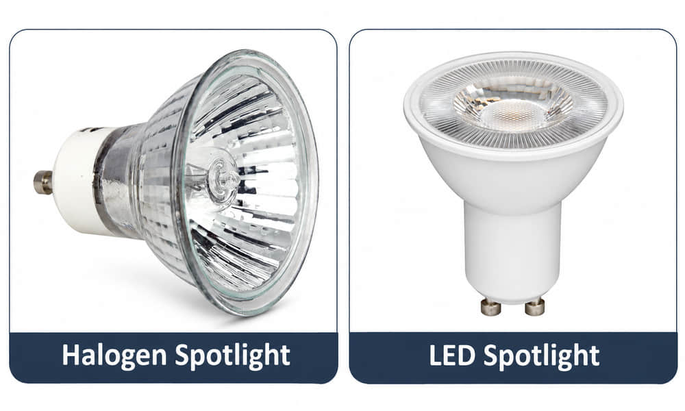
A halogen reflector works with a filament of a particular size and position. An LED optical system works with a different emitting surface and angular distribution. Changing the source changes what the optic must collect and redirect.
The nominal LED package size is only an initial compatibility check. Two LEDs in the same package format can have different emitting areas or primary optics. With a given secondary optic, a larger emitting area can make a narrow beam harder to achieve and alter the central peak and transition.
Neither technology has one fixed visual signature. Halogen systems can produce filament images or uneven edges; LED systems can produce smooth transitions, sharply controlled beams or visible structure. The result depends on the complete optical design, not simply the source technology.
For compact LED spotlight development, Asahi’s architectural lighting single lenses include the AF Series, listed with a 21.3 mm diameter and round and oval distribution options. This provides a component family to investigate when optical space is limited. Selection still depends on the intended LED and mounting geometry; these lenses are not finished halogen replacement lamps.
Match Color Appearance Separately from Beam Shape
A beam can match geometrically while making the illuminated object look different. Similar correlated color temperature does not establish that two sources have the same spectrum or render merchandise identically.
Use CCT and CRI for an initial comparison, then examine representative materials under both spotlights. Red fabrics, wood finishes, skin tones and reflective packaging can reveal differences that are not obvious on a white wall.
Where color appearance is critical, request TM-30 information rather than relying on one CRI value. The IES explanation of color-rendition specification describes how fidelity, gamut and hue-related information provide a more detailed picture of a source’s effect on colors.
If the installation normally operates dimmed, include that operating scene in the comparison. A satisfactory match at full output does not establish a match at the setting customers will actually see.
Run a Side-by-Side Comparison That Supports a Decision
Compare both spotlights in the intended geometry. A beam photograph on a nearby wall cannot establish performance on a tilted display several metres away.
- Fix the setup. Keep the mounting position, aiming point, target surface and surrounding lighting unchanged. Record each product’s operating setting and allow its output to stabilize.
- Measure the target and background. Use the same marked measurement grid for both products. Include the center, relevant edges and selected positions outside the intended accent.
- Check from normal viewing positions. Look for distracting source visibility, reflected glare, shadows, rings and color variation across the object.
- Document the comparison consistently. Keep camera exposure and white balance fixed and avoid clipped highlights. Use photographs to document appearance, not as substitutes for lux readings.
For oblique illumination, use the actual source-to-target distances and target orientation in the calculation. Points near the top and bottom of a display may differ in distance and incidence angle, so a round angular distribution need not produce an evenly lit round patch on the surface.
When reviewing photometric files, compare absolute candela values as well as curve shape. Two curves normalized to the same peak can look similar while representing different delivered intensity. For a non-circular distribution, inspect both principal planes.
Use the Mismatch to Choose the Next Adjustment
The center matches, but the display edges are darker
Check the intermediate and edge readings before increasing power. If the center already meets the requirement, more output may create a hotspot without correcting the distribution. Review a broader shoulder distribution, a different beam shape or the aiming geometry.
The object is bright enough, but no longer stands out
Compare the background readings. Excess peripheral light may be raising the surrounding illumination and reducing visual emphasis. Investigate off-axis control, shielding or a different distribution before increasing center intensity.
On the same unchanged surface, target-to-background illuminance readings can help diagnose this change. They are not a universal measure of perceived contrast: surface reflectance, gloss and viewing direction also affect appearance.
The beam is displaced or uneven
First confirm the fixture aim. In an OEM prototype, then inspect LED centering, holder location, lens seating and tilt. A pattern that changes when a component is reseated points toward an assembly issue; a repeatable pattern in a correctly assembled system calls for optical review.
Color or surface appearance changes across the beam
Compare the source without the secondary optic, where safely accessible during development, and then with the complete optical assembly. This helps separate source-related angular color variation from changes introduced by the lens, cover or other optical paths.
A mixing feature may improve appearance, but it can also change intensity and beam width. Evaluate that trade-off against the target requirements rather than treating diffusion as an automatic correction.
Find an Optic Around the Required Lighting Effect
For an LED spotlight project, send Asahi Optics the LED part number, target dimensions, working distance, aiming arrangement and available optical space. If you are matching an existing halogen installation, include its lamp reference and any useful photographs or photometric data.
Request an existing-lens assessment to identify candidate optics, obvious source or mounting compatibility constraints, and the additional information needed for evaluation. The starting point is the lighting effect you need to retain—not a wattage-equivalence label.