The modern linear lighting landscape is characterized by increasing architectural integration, slim structural profiles, and strict optical performance requirements. As luminaire manufacturers, lighting contractors, and commercial brand managers strive to deliver sophisticated linear lighting systems, the physical execution of these luminaires often runs into unexpected manufacturing hurdles.
In the traditional procurement model, sourcing a linear lighting system requires procuring the optical extrusion lens from one specialized optical component manufacturer and the structural aluminum housing from a separate profile extruder. On paper, this division of labor appears logical. In practice, however, it introduces systemic friction into the engineering and supply chain processes.
When linear optics and structural profiles are designed and manufactured in isolation, luminaire assemblers bear the burden of cross-vendor calibration. Minor dimensional variances, differing thermal expansion coefficients, uncoordinated lead times, and optical beam clipping frequently derail project schedules and inflate production costs.
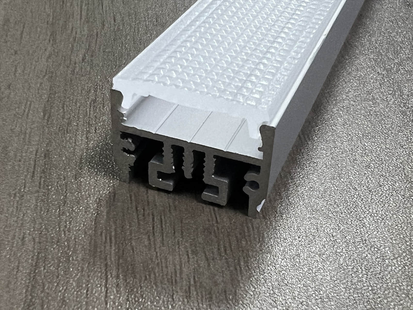
The industry does not simply require a standalone plastic lens or an isolated aluminum extrusion; it demands a fully integrated, pre-engineered linear optical assembly. Our integrated extrusion lens and matched profile solution addresses these supply chain inefficiencies directly. By unifying optical engineering, mechanical tool design, and production scheduling under a single manufacturing ecosystem, we eliminate component mismatch and streamline the procurement lifecycle from initial blueprint to final assembly.
The Hidden Costs of Fragmented Lens and Profile Procurement
In linear luminaire manufacturing, the true cost of a component is rarely reflected in the purchase order unit price alone. The hidden engineering and logistical expenses incurred when coordinating between separate optical and mechanical vendors often outweigh initial component savings.
Mechanical Tolerance Drift and Assembly Friction
Plastic extrusion and aluminum extrusion operate under fundamentally different manufacturing environments, material behaviors, and processing tolerances. Polymethyl methacrylate (PMMA) or polycarbonate (PC) optical lenses undergo volumetric contraction during thermal cooling, while 6063-T5 aluminum profiles experience different thermal contraction rates as they emerge from the extrusion die and cooling tanks.
When Vendor A designs an optical lens and Vendor B extrudes an aluminum channel using separate internal engineering standards, mechanical tolerance stack-up is virtually inevitable:
-
The Over-Sized Lens Dilemma: If the plastic lens profile trends toward the upper limit of its dimensional tolerance band while the aluminum retention track trends toward its lower limit, assembly workers must apply excessive physical force to slide or snap the lens into place. This frequently causes stress cracking, micro-fractures along the retention feet, or localized optical distortion.
-
The Under-Sized Lens Dilemma: Conversely, if the lens trends small and the housing channel trends large, the optical cover fits loosely inside the track. This results in audible vibration rattling when exposed to nearby HVAC circulation, poor dust ingress protection (IP rating failure), and physical lens sagging over extended linear runs.
Resolving these physical fit issues across two independent suppliers requires multiple rounds of re-tooling, sample iterations, and inter-company debate regarding which vendor's drawings were out of specification.
Unintended Optical Interference and Vignetting
An optical lens designed in a "free-space" computer simulation performs predictably under ideal conditions. However, once that lens is mechanically recessed into an aluminum profile housing, the surrounding mechanical walls alter the light distribution path.
If the aluminum housing supplier alters the depth of the channel, the thickness of the retaining lip, or the interior reflectivity of the metal wall without consulting the optical engineer, the housing physically clips the peripheral light rays emitted by the lens. This optical interference introduces several performance flaws:
-
Luminous Efficacy Losses: Internal clipping traps emitted lumens inside the profile cavity, dramatically lowering the overall light output ratio (LOR) of the luminaire.
-
Cut-off Shadowing and Artifacts: Sharp internal profile edges cast unwanted hard shadow lines along the perimeter of the beam angle, replacing a smooth light distribution with visible optical banding on target surfaces.
-
Secondary Stray Glare: Light reflecting off unoptimized interior aluminum walls can escape through the lens exit aperture at sharp angles, creating visual discomfort and violating unified glare rating (UGR) specifications.
Unsynchronized Supply Chains and Administrative Overhead
Managing separate vendors for lenses and housings doubles the administrative and operational workload for procurement departments:
-
Staggered Lead Times: If the optical lens arrives at the assembly plant on week four, but the matching aluminum profiles are delayed until week eight due to anodizing or raw billet shortages, the assembly line sits idle. Storage space is consumed by half-finished inventory, and customer delivery commitments are compromised.
-
Divided Quality Accountability: When a fully assembled linear fixture exhibits light leaks, rattling components, or poor egress protection during final quality control, identifying the root cause becomes problematic. The lens vendor blames the profile tolerances, while the profile vendor points to the plastic lens contraction. The customer is left to mediate the technical dispute while project deadlines loom.
Our integrated approach transforms this fragmented process into a unified, single-source workflow. Every optical lens profile is engineered, validated, and manufactured alongside its corresponding structural housing, guaranteeing instant physical compatibility, pristine optical delivery, and synchronized delivery schedules.
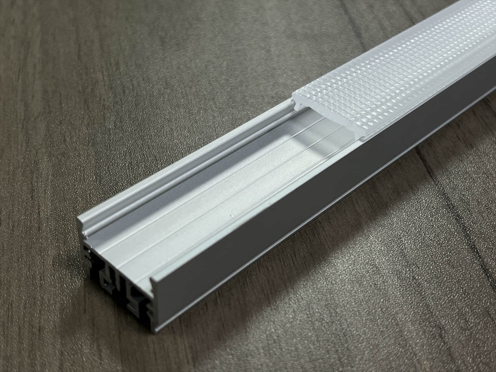
Integrated Engineering: Eliminating Mechanical Tolerance and Optical Interference
The core strength of our integrated solution lies in unified product development. Rather than treating the extruded optical lens and the aluminum housing as separate entities that meet for the first time on the customer's assembly line, our engineering teams treat them as two interdependent halves of a single, coherent linear lighting module.
Dual-Interface Tolerance Matching in One Design Environment
When engineering a new optical profile, our mechanical designers simultaneously draft the mating geometry of the aluminum track. We do not rely on generic industry clearances. Instead, we calculate the exact interference fit by factoring in the viscoelastic properties of optical-grade PMMA/PC alongside the structural tolerances of extruded 6063-T5 aluminum.
-
Elastic Snap-Fit Kinetics: Our retention channels are engineered with calculated lead-in chamfers and elastic deflection zones. The lens snap feet flex predictably during insertion, dropping into the aluminum groove with an audible click. This provides tactile feedback for assembly line operators while maintaining constant positive pressure against the profile wall to eliminate noise and movement.
-
Controlled Thermal Expansion Cavities: Because plastic expands at a higher linear rate than aluminum under elevated operating temperatures, our integrated channels incorporate expansion gaps at the terminal joints. This prevents longitudinal warping or bowing of the lens when linear fixtures run at maximum thermal capacity over long durations.
Ray-Tracing Simulations with Housing Geometry Included
To prevent optical vignetting and efficiency losses, our optical engineers conduct photometrical ray-tracing simulations using software like LightTools that incorporate the complete physical model of the matching aluminum housing.
-
Ray Tracing Beyond the Lens: The reflective properties, wall heights, interior draft angles, and lip dimensions of the aluminum housing are treated as active variables in the optical simulation.
-
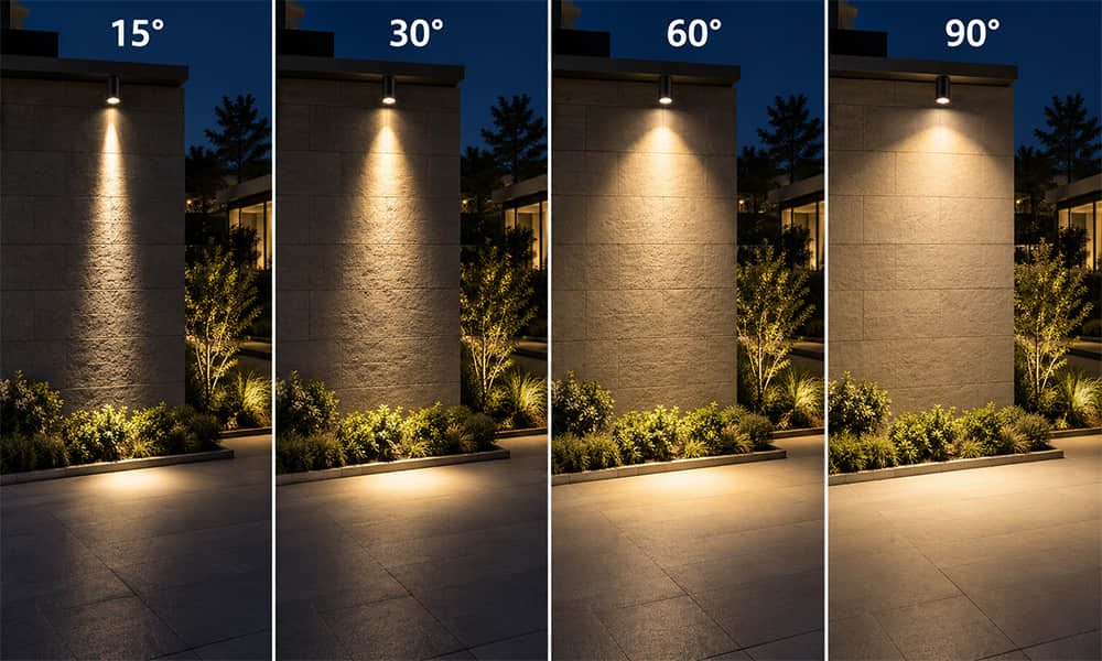
Eliminating Beam Clipping: If a wide beam distribution (such as a 120∘120∘ diffuse throw or a 145∘145∘ batwing pattern) approaches the edge of the aluminum profile, the internal housing wall is angled outwards or recessed during the initial drawing phase. This ensures that the housing never intersects the primary beam trajectory, preserving maximum total luminous flux (LOR>92%LOR>92%) and maintaining smooth intensity gradients without hard shadow cut-offs.
Synchronized Supply Chain: One Order, One Delivery, One Quality Standard
Consolidating your linear optical components under a single manufacturing ecosystem replaces complex vendor management with an efficient, single-source procurement workflow. The table below illustrates the operational advantages of transitioning from a split-vendor model to an integrated solution:
| Operational Metric | Fragmented Model (Lens Vendor A + Profile Vendor B) | Integrated Solution (One Unified Supplier) |
| Vendor Management | Two separate contracts, separate POs, dual communication channels | Single PO, one technical contact, simplified account management |
| Engineering Verification | Customer manually tests compatibility; vendors debate discrepancies | Pre-validated by supplier; arrives guaranteed to fit |
| Sample Iteration Cycle | Staggered sampling; testing delayed until both samples arrive | Simultaneous prototyping; complete, functional module delivered together |
| Quality & Defect Ownership | Fragmented accountability; high risk of inter-vendor blame | Single-source responsibility covering both optics and structural housing |
| Logistics & Delivery | Split shipments, unaligned lead times, double freight fees | Synchronized packaging, single arrival date, lower shipping overhead |
| Assembly Readiness | High risk of line stoppage due to missing half of the system | Immediate assembly; unbox and integrate directly into luminaires |
Custom Co-Extrusion & Tooling: Tailoring Integrated Systems for Non-Standard Projects
While standardized lens and profile combinations serve a broad range of architectural applications, specialized lighting projects frequently require bespoke optical distributions, unique mounting mechanics, or custom physical footprints. Rather than forcing your design into off-the-shelf constraints, our facility provides end-to-end custom tooling for both components simultaneously.
-
Tailored Optical Distributions: If your luminaire design demands an ultra-narrow wall-grazing beam, a dual-asymmetric aisle distribution, or a low-glare micro-prismatic glare reduction pattern, our optical engineers design the freeform lens surfaces from the ground up. We select the ideal base polymer—utilizing high-transmittance optical PMMA or impact-resistant, glow-wire compliant PC—and incorporate specialized scattering agents to balance diode hiding power with optical efficiency.
-
Custom Architectural Aluminum Section Profiles: Concurrently, our mechanical division dies and extrudes custom 6063-T5 aluminum sections tailored to your structural mounting requirements. Whether your project calls for ultra-slim trimless plaster-in channels, magnetic track integration, heavy-duty exterior recessed housings, or decorative curved profiles, the interior lock tracks are designed alongside the custom lens.
-
Simultaneous Die Cutting and Joint Trial Extrusions: Unlike traditional tooling processes where the plastic extrusion die and aluminum die are cut at different facilities weeks apart, our internal tooling room produces both die sets simultaneously. Joint trial extrusions are performed in-house: the freshly extruded optical lens is tested directly against the first-article aluminum section. Any minor dimensional adjustments are corrected internally before mass production begins, ensuring your custom non-standard system is delivered ready for deployment.
Technical Specification Matrix for Integrated Systems
To assist lighting designers and procurement managers in evaluating standard manufacturing limits, the table below summarizes our technical processing capabilities for integrated linear optics and profile sets:
| Parameter Category | Extruded Optical Lens | Structural Aluminum Housing | Integrated System Advantage |
| Material Base | Optical PMMA / UV-Stabilized PC | 6063-T5 Structural Aluminum | Matched thermal expansion rates |
| Standard Width Range | 7mm-40mm | 9mm-42mm | Engineered zero-clearance snap tracks |
| Optical Distribution | 30°, 60°,90°,145°Batwing, Asymmetric | Open / Recessed / Flanged Sections | Zero internal wall beam clipping (LOR > 92%) |
| Surface Finish | Micro-prismatic / Diffuse / Clear | Anodized Silver / Powder-Coated Black / White | Consistent visual styling and color harmony |
| Delivery Format | Custom-cut linear lengths (1m-3m) | Custom-cut linear lengths (1m-3m) | Synchronized single-pallet shipments |
Conclusion
In the fast-paced linear lighting market, spending engineering hours and procurement cycles mediating technical disputes between separate optics and aluminum vendors is an unnecessary drain on company resources.
Linear lighting performance relies on complete mechanical and optical harmony. Our Extruded Lens + Profile Solution delivers an integrated, pre-engineered optical module that arrives at your factory floor ready to assemble. By combining precision optical extrusion, structural aluminum section design, synchronized production scheduling, and custom co-tooling capabilities under one roof, we eliminate cross-vendor tolerances and streamline your manufacturing pipeline.
Stop matching standalone lenses to third-party housings. One order, one system, one supplier—contact our engineering desk today to request a matched sample evaluation kit or submit your project drawings for an integrated system review.
FAQ
Q1: Do you supply both the extruded lens and the aluminum profile together as a matched set?
A: Yes, we provide pre-matched lens and aluminum profile sets engineered to fit seamlessly out of the box.
Q2: Can the lens and profile be ordered separately if we already have one of the components in-house?
A: Yes, we can custom-extrude either a matching optical lens or an aluminum housing to fit your existing CAD dimensions.
Q3: What is the minimum order quantity (MOQ) and lead time for a custom lens + profile combination?
A: Custom joint development typically requires an MOQ of 1,000 meters with a tooling and validation lead time of 3 to 4 weeks.
Q4: How do I know if a standard lens will fit an existing profile without conducting physical tests?
A: Our engineering team provides STEP 3D files and performs digital CAD clearance checks prior to sample production.
Q5: Can you provide pre-assembled evaluation samples of the matched set before we commit to mass production?
A: Yes, we supply 1-meter pre-cut sample kits containing the matched lens, aluminum profile, end-caps, and mounting clips.
Q6: How does the pricing of an integrated solution compare to buying lenses and profiles separately from different suppliers?
A: While individual unit prices are similar, an integrated solution lowers total manufacturing costs by eliminating cross-vendor re-tooling, split shipping, and assembly scrap.