In the sterile, controlled environment of a photometric lab, achieving high lumen output is relatively straightforward. However, when a luminaire is mounted 10 meters above a wet asphalt road, flanked by residential windows and subjected to variable pole spacing, raw power becomes irrelevant. What matters is control.
Engineers and lighting designers frequently encounter three persistent challenges that ruin the performance of an otherwise efficient fixture: the Zebra Effect (poor longitudinal uniformity), Light Trespass (backlight invading private property), and the White Wall phenomenon in adverse weather. These are not merely aesthetic complaints; they are safety hazards and liability issues.
Solving these problems requires a shift from simple illumination to Precision Optical Engineering. It demands the use of sophisticated secondary optics—specifically designed using Free-form Surface technology—and rigorous validation through computer-aided simulation. By utilizing advanced ray-tracing software and photometric modeling (DIALux), we can mathematically predict and correct light behavior before a single physical prototype is ever built. This article explores the optical logic behind these three common issues and demonstrates how simulation-driven lens design provides the definitive solution.
1. The Zebra Effect (Longitudinal Uniformity)
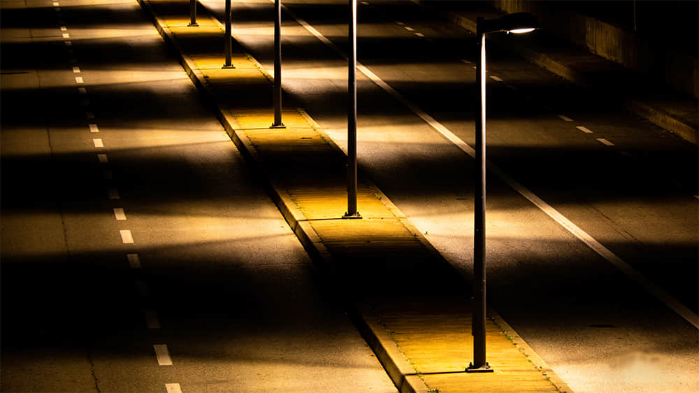
One of the most dangerous flaws in street lighting is the Zebra Effect—a pattern of alternating bright pools under the poles and dark shadows in between. In lighting metrics, this is a failure of Longitudinal Uniformity ($U_l$). When a driver moves through these high-contrast zones at speed, the rapid fluctuation in luminance forces the pupil to constantly expand and contract, leading to visual fatigue and delayed reaction times.
The Optical Solution: Free-form Surface & Batwing Distribution
The root cause is a lens that concentrates too much light directly below the fixture. To solve this, optical engineers employ Free-form Surface technology. Unlike simple spherical lenses, a free-form lens surface is calculated using complex algorithms to create a Batwing Light Distribution, where peak intensity is pushed out to high angles (typically 60° to 65°).
-
Refraction Logic: The inner lens surface captures the LED's output, while the precisely curved outer surface refracts rays laterally.
-
Result: This design stretches the light footprint, pushing photons to the midpoint between poles, ensuring nearly equal light levels at the furthest point and directly under the fixture.
Simulation Verification
This performance is verified through Ray Tracing Simulation before any mold is cut.
-
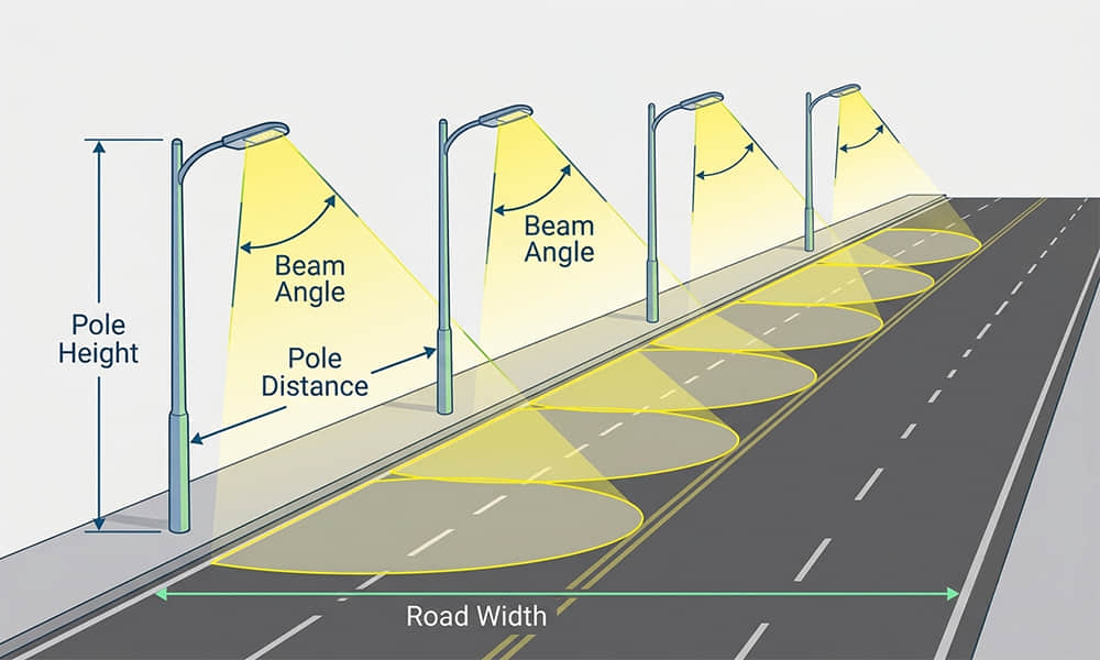
Software simulates millions of light rays, replicating specific road geometry (e.g., 10m pole height, 35m spacing).
-
Target Metric: The lens geometry is iterated until the calculated Longitudinal Uniformity ($U_l$) exceeds 0.7.
-
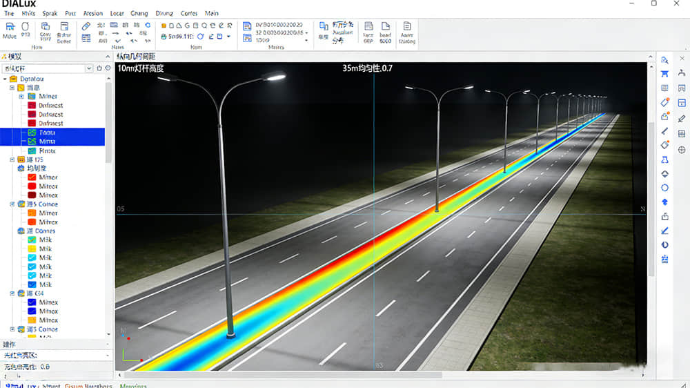
False Color Analysis: In DIALux, a successful simulation shows a continuous band of color along the driving lane, eliminating patches of red (bright) and blue (dark).
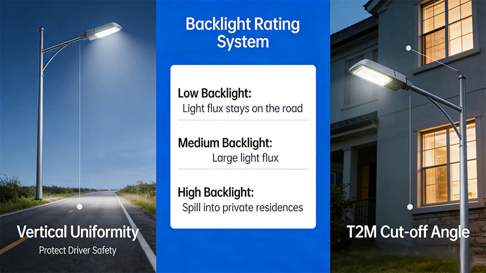
2. Backlight Control & Light Trespass
While longitudinal uniformity ensures driver safety, Backlight (House-side Light) determines community livability. This is quantified by the BUG Rating system. A high Backlight rating means wasted lumens are spilling onto private property.
This is a complex optical challenge: redirecting the 50% of light that naturally goes backward forward, without losing efficiency. Modern solutions achieve this within the lens itself.
The Optical Solution: Integrated TIR Prisms & Cut-off Design
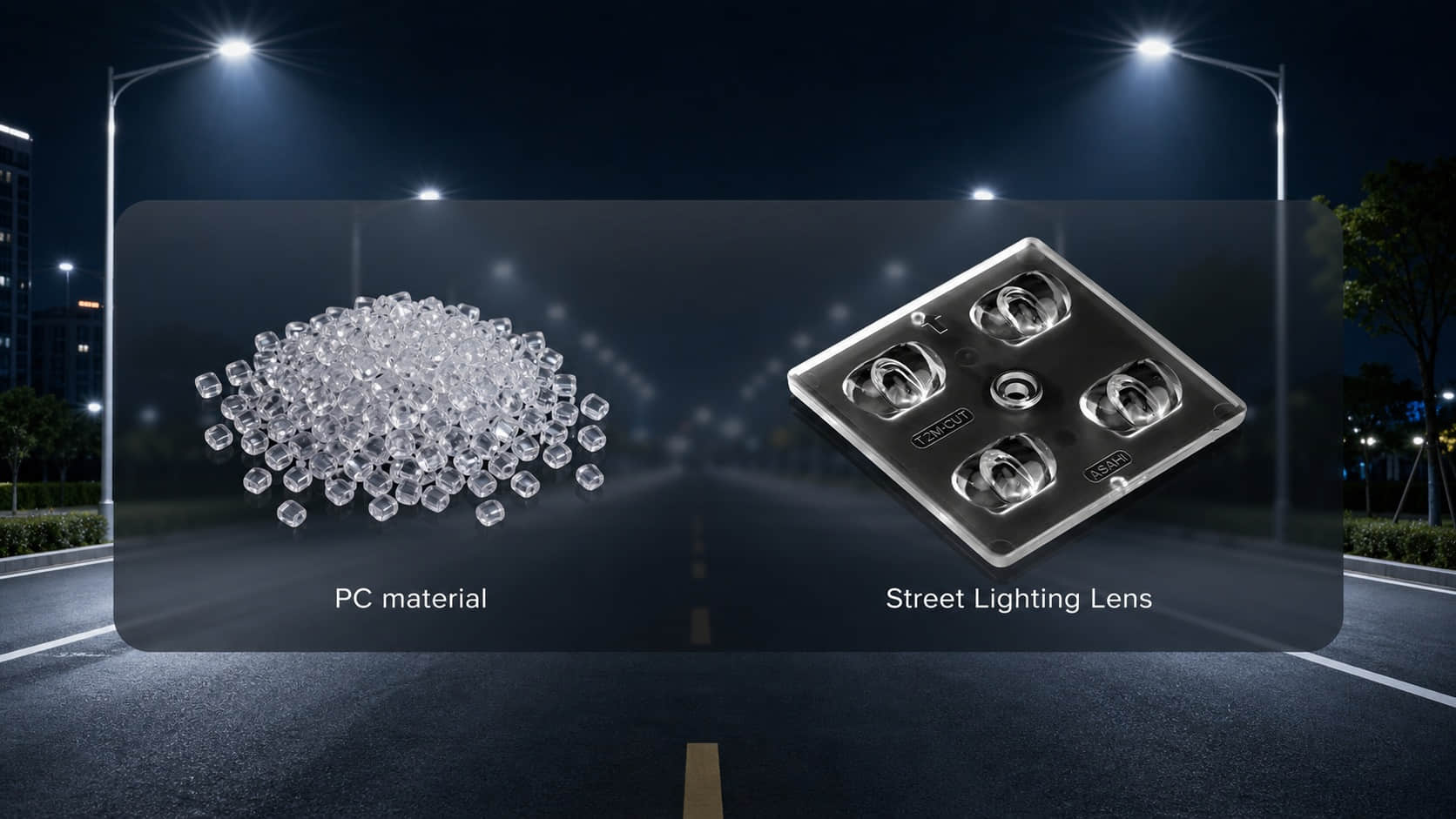
Modern suppression of light trespass relies on Total Internal Reflection (TIR) within the lens structure. A specific prism structure on the house-side face of the optic is engineered for this purpose.
-
The Mechanism: Light rays hit these calculated prism angles. The angle of incidence exceeds the critical angle of the polycarbonate material, causing the light to bounce internally and be redirected.
-
The Result (Hard Cut-off): This creates a hard cut in the light distribution, with intensity on the house side dropping sharply to near zero at critical angles behind the pole.
Product Application: Precision T2M Solutions
Asahi Optics utilizes simulation to offer distinct solutions for different street scenarios:
-
The Hard Stop Solution (Model ALST173D12LED5050T3M): For poles adjacent to residential windows. Features an aggressive T2M-Cutoff angle to physically restrict high-angle backlight.
-
The Balanced Solution (Model ALST173D12LED5050T2M): For urban areas needing sidewalk visibility. Offers a T2M With Backlight configuration, allowing controlled light for pedestrian safety without excessive glare.
3. The White Wall Effect (Weather Penetration)
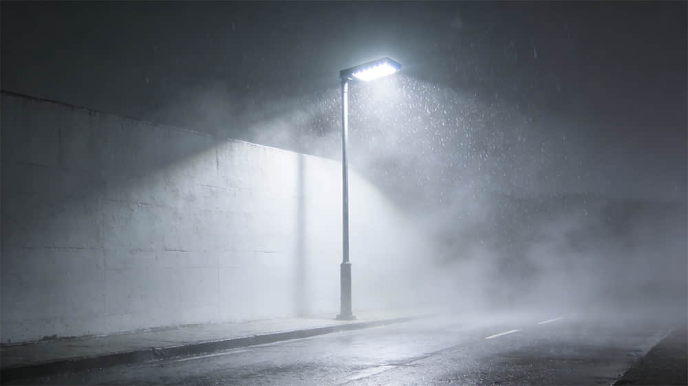
In regions with heavy rain, fog, or snow, standard LED street lights can create the dangerous White Wall effect. High-intensity light scatters off airborne water droplets back towards the driver, obscuring the road.
The Physics: Mie Scattering & Optical Control
While CCT choice matters, the Optical Lens is critical. The effect is caused by Stray Light emitted at high, near-horizontal angles, illuminating fog in the driver's sightline.
The Optical Solution
Precision optics must minimize upward waste light. High-quality lenses, like Asahi’s street lighting series, feature polished surfaces and calculated TIR angles to tightly control the beam downwards. This reduces illuminated fog volume in front of the driver, increasing the Contrast Ratio of road objects.
The Role of Virtual Prototyping: Why Simulation Matters?
Historically, solving these challenges required costly trial and error. Today, Virtual Prototyping revolutionizes the industry.
-
Optical Ray Tracing: Software simulates millions of photons to detect and instantly correct errant light paths in the CAD model.
-
Application Simulation: Virtual lenses are imported into DIALux to model entire streetscapes, allowing performance validation under various conditions (pole height, spacing).
This Simulation-First approach ensures that an Asahi lens delivers calculated, certain performance, not guesswork.
Conclusion
Street lighting is an exercise in balancing driver safety, resident comfort, and environmental adaptability. Solving the Zebra Effect, Light Trespass, and White Wall issues cannot be achieved with higher wattages alone. The solution lies within the Optical Lens.
By leveraging Free-form Surface technology and validating designs through rigorous Ray Tracing and DIALux simulations, manufacturers can achieve true optical precision. Simulation turns the behavior of light into a predictable engineering standard, ensuring the road ahead is not just lit, but mastered.