1. What is LED Lighting?
To understand the critical role of an optical lens, we must first understand the fundamental nature of the light source itself.
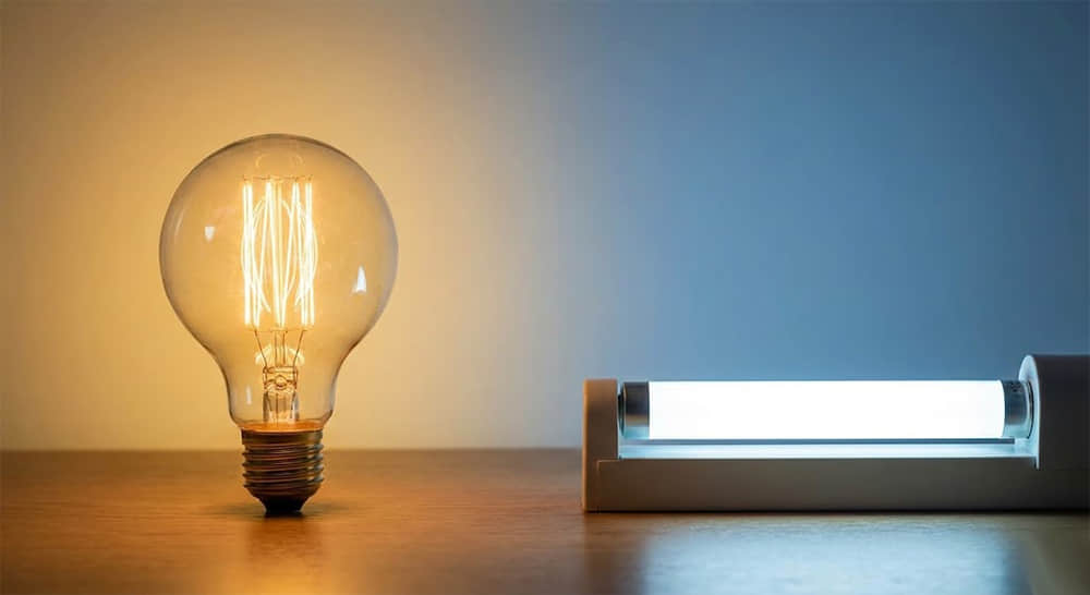
For over a century, artificial lighting was defined by incandescence—the process of heating a tungsten filament until it glowed. In this "analog" era, the light source was essentially a heater that produced light as a byproduct. Today, we have transitioned to the era of Solid-State Lighting (SSL).
LED (Light Emitting Diode) is not a bulb in the traditional sense; it is a semiconductor device that converts electricity directly into light through a process called Electroluminescence.
1.1 The Physics of Electroluminescence
Unlike traditional light sources that rely on heat (incandescent) or gas discharge (fluorescent), an LED creates light within a solid block of material.
At the heart of every LED fixture—whether it is a street light or a high-bay lamp—is a tiny chip, typically made from semiconductor materials like Gallium Nitride (GaN). This chip contains two distinct layers:
-The N-type layer: Loaded with extra electrons (negative charge).
-The P-type layer: Loaded with "holes" (positive charge).
When a forward voltage is applied via the LED Driver, electrons are pushed across the boundary (the P-N junction). As an electron falls into a hole, it drops to a lower energy state. The excess energy is released in the form of a packet of light—a photon.
This process is incredibly efficient because it bypasses the "heat" stage of light generation. However, this efficiency comes with a unique characteristic that dictates the entire design of the fixture: The light is generated from a flat surface, not a spherical bulb.
1.2 Generating White Light: The "Blue Pump" Method
It is important for buyers and engineers to understand that LEDs do not naturally emit white light. A raw LED chip is monochromatic (usually blue).
To create the white light needed for street lighting (typically 3000K to 5700K CCT), manufacturers coat the blue LED chip with a Yellow Phosphor layer (Yttrium Aluminum Garnet). The blue light excites the phosphor, which then emits yellow light. The mixture of the transmitted blue light and the emitted yellow light appears white to the human eye.
Why does this matter for optics? This "Blue + Phosphor" structure creates a challenge known as "Color over Angle" (CoA) or the "Yellow Ring" effect. Without a precision-engineered Optical Lens, the light at the edges of the beam can appear noticeably yellower than the light in the center.
High-quality lenses, such as Asahi Optics' COB or SMD series, are designed with specific surface micro-structures to mix this light output, ensuring that the color temperature remains consistent across the entire illuminated area.
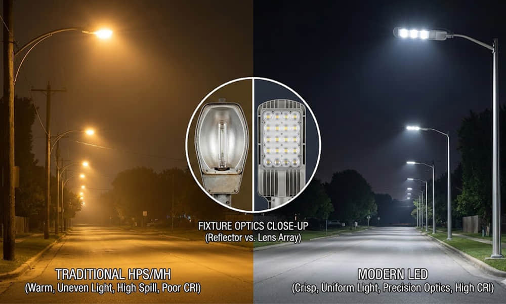
1.3 LED vs. Traditional Sources: A Fundamental Difference
The transition to LED is often compared to the transition from vacuum tubes to transistors.
- Incandescent/Halogen: These are "Omnidirectional" sources. They emit light in 360 degrees. Controlling this light requires bulky, inefficient reflectors that trap nearly 40% of the lumens inside the fixture.
- LED (Solid State): This is a "Directional" source. A raw LED chip emits light in a specific forward direction, typically in a 120° cone (known as a Lambertian distribution).
While this directionality makes LEDs inherently more efficient than bulbs (because you aren't lighting up the inside of the fixture), a 120° beam is still too wide for most applications. If you mount a raw LED on a 10-meter street light pole, the light will spread too thin, failing to reach the required lux levels on the pavement while blinding drivers with high-intensity glare.
This is the defining paradox of LED lighting: The LED chip provides the potential for high efficiency, but it is the Optical Lens that converts that potential into usable performance. The chip is the engine, but the lens is the transmission that puts the power to the road.
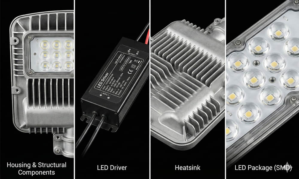
2. The Mechanics of LED: Pros, Cons, and Components
In reality, a modern LED street light or high-bay fixture is a sophisticated electronic device, more akin to a computer than a traditional lamp. Unlike a fluorescent tube that works independently, an LED chip is fragile and dependent on its environment. Its performance relies on the synergy of four critical subsystems.
The Anatomy of an LED System: The Light Source、The Thermal Management System、The Driver(power supply)、The Secondary Optics
Learn more about LED Luminaire Components
2.1 Why Choose LED? The Undeniable Advantages
The global shift to LED lighting is driven by three key factors that directly impact ROI (Return on Investment):
-
System Efficacy (lm/W): Modern LED packages can exceed 200 lm/W. However, the final "System Efficacy" depends on the optical efficiency. A high-quality lens from Asahi Optics typically maintains a transmittance rate of >93%, ensuring that the raw power of the chip translates into usable light.
-
Longevity (L70): A well-engineered fixture can last 50,000 to 100,000 hours before its light output degrades to 70%.
-
Compact Form Factor: The small size of LED chips allows for sleek, aerodynamic designs—like our Linear Lens series—that were impossible with bulky traditional bulbs.
2.2 The Hidden Disadvantages: Why "Raw" LEDs Fail
Despite these advantages, using a "Raw LED" (an LED chip without a secondary lens) is almost never a viable solution for professional lighting. Here is why:
-
The "Lambertian" Problem (Spill Light): A raw LED emits light in a Lambertian Distribution. Imagine a garden hose spraying water in a wide, uncontrolled mist.
-
In Street Lighting: If you mount raw LEDs on a 12-meter pole, the light will spread 120 degrees wide. About 40% of that light will land on the surrounding fields or the night sky (Light Pollution), rather than the road. This is wasted energy.
-
-
The Glare Hazard (UGR): LEDs have an extremely high surface brightness (Luminance). Millions of nits are concentrated in a tiny 3mm x 3mm square.
-
Looking directly at a raw LED is painful and dangerous. In an office or warehouse, this creates a high UGR (Unified Glare Rating), causing eye strain and reducing productivity.
-
-
Limited Throw Distance: Because the light spreads out so quickly, the intensity (candela) drops off rapidly over distance. A raw LED cannot effectively illuminate objects further than a few meters away
In summary, while the LED chip provides the efficient photon generation, it inherently lacks photon control. This limitation is the primary reason why Optical Lens Design has become the most critical discipline in modern luminaire manufacturing.
3. How an LED Lens Works: The Science of TIR
So, how do we tame the unruly 120° beam of a raw LED? The answer is a principle called Total Internal Reflection (TIR).
While traditional lighting used “Reflectors” which lose nearly 20-30% of light to absorption, modern LED lenses utilize TIR to capture virtually 100% of the emitted photons.
A TIR lens, typically molded from optical-grade PMMA or PC, sits snugly over the LED chip. It consists of two zones:
-
The Central Lens: A refractive surface that focuses the direct light.
-
The Sidewall: A curved surface engineered to reflect the spill light forward using internal physics, not metallic coatings.
By calculating the precise curvature of these surfaces, Asahi Optics can collimate the scattered light into a tight parallel beam or shape it into specific patterns. This optical efficiency allows our lenses to achieve a light transmittance rate of over 92%, ensuring that every watt of energy you pay for is delivered to the target surface.
4. Deep Analysis: The Critical Difference & Fixture Categorization
The difference between a fixture with and without a lens is not just aesthetic; it is functional. It is the difference between general "illumination" and precision “lighting control.”
To help you decide if your project requires an optical lens, we have categorized common LED fixtures into two groups: those that rely on simple diffusers and those that demand precision optics.
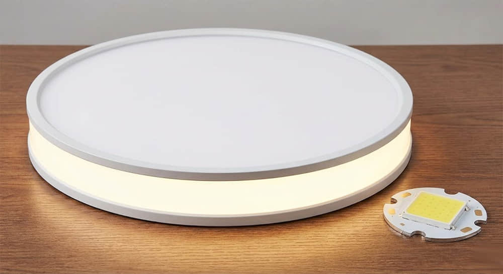
4.1 Fixtures That Typically Do NOT Use Optical Lenses
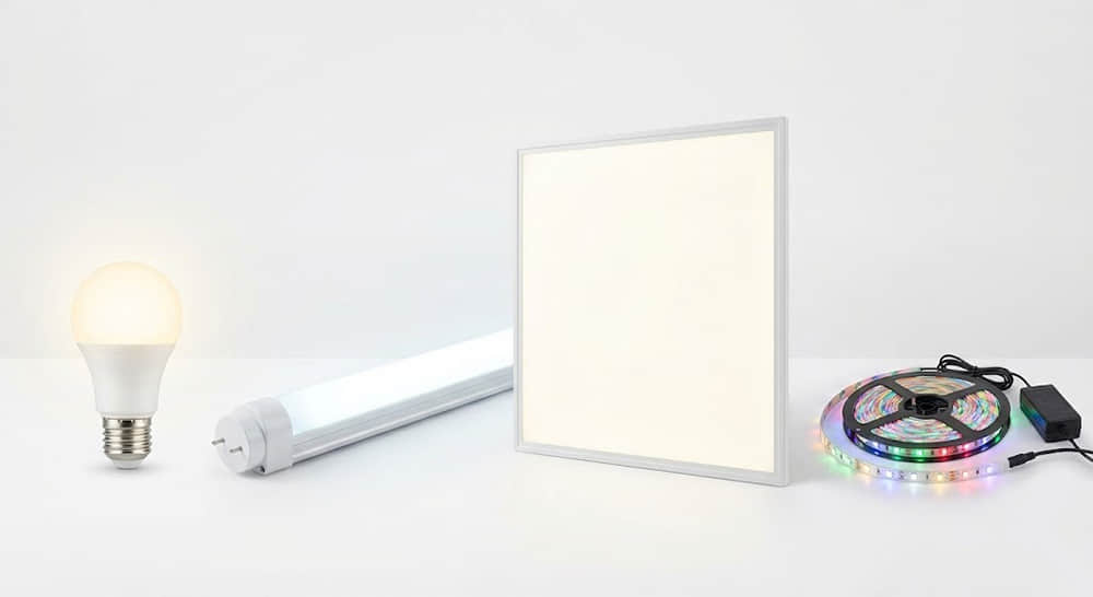
In these applications, the goal is usually omnidirectional light or simple soft glow. Precision control is not the priority; cost and general coverage are. Instead of TIR lenses, these fixtures typically use Opalescent Diffusers (milky white plastic covers) or simple aluminum reflectors.
4.2 Fixtures That MUST Use Optical Lenses
In these applications, "spill light" is unacceptable. You need to throw light over a long distance, shape it into a specific pattern, or meet strict government regulations (like IESNA standards).
Street Lights
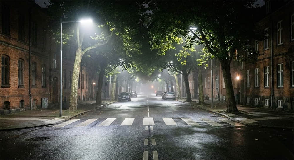
You cannot simply "light up" a road; you must project a rectangular beam that covers the asphalt while cutting off light to the sky. If you install raw LEDs (120° beam) on a street pole, you create two major problems:
- The Zebra Effect: You get a bright hot spot directly under the pole and darkness in between poles. This alternating bright-dark pattern creates visual fatigue and danger for drivers.
- Light Trespass: A massive amount of light spills backward into residential windows or upward into the sky (Sky Glow).
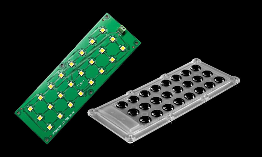
Recommend the Street Light Multi-Modules Lens. These create Type II or Type III beam patterns, ensuring uniform luminance between poles spaced 30-50 meters apart. It achieves Longitudinal Uniformity (Ul) of >0.7, eliminating the zebra effect and allowing poles to be spaced up to 4 times their height apart.
High Bay & Low Bay Fixtures (Industrial)
In a warehouse with 10-meter ceilings, workers look up constantly. A raw high-power LED bay light is a blinding glare bomb. Furthermore, much of the light hits the top of the racking shelves rather than the floor where the forklifts operate. You need a "Deep Shielding" lens or a specific beam angle (60° or 90°) to cut off side glare.
Recommend the UFO High Bay Lens, ranging from 110mm to 344mm in diameter. By narrowing the beam, we punch the light down to the working floor, significantly increasing the lux levels and reducing glare for forklift drivers.
Wall Washers & Facade Lighting
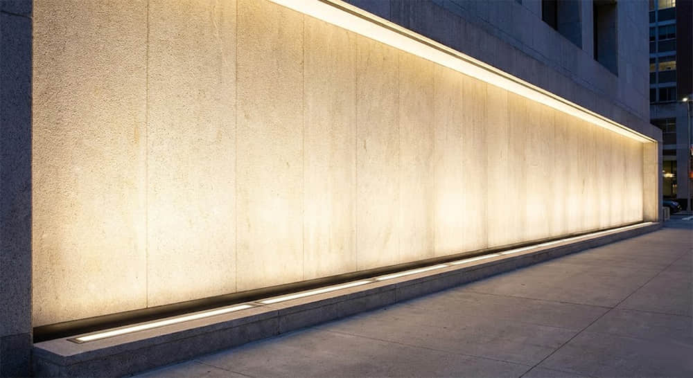
Architects want to illuminate a vertical wall evenly from bottom to top without "spilling" light sideways. A raw LED cannot do this; it just creates a fuzzy blob.
Recommend the Single Lens Series. This series not only features an extremely compact lens size (10mm in diameter) but also includes multiple narrow beam angles (10°, 13°, 15°, 25°). Designed to achieve uniform vertical wall illumination without light "spillover" to the sides, its precise light distribution acts like a sharp "light blade."
5. How to Select the Right Optical Lens?
Knowing you need a lens is step one. Choosing the right one is step two. As a mold manufacturer and optical design company, Asahi Optics recommends evaluating three key factors:
5.1 The Beam Angle (IES Distribution)
Do not just ask for "a lens." Specify the distribution. For example, in street lighting, light distribution patterns (Type I–Type V); in other applications, single-angle, dual-angle, polarized, or asymmetric beam distributions. Different lighting requirements call for matching different beam angles.
5.2 Material Science: PC vs. PMMA
Material selection can be based on the specific lighting project. Below is a basic introduction to two common materials:
-
PMMA (Acrylic):
-
Advantages: High light transmittance (approx. 93%), excellent UV resistance (does not yellow).
-
Best suited for: Architectural lighting, indoor lighting, and general street lighting in mild climates.
-
-
PC (Polycarbonate):
-
Advantages: Virtually unbreakable (IK10), high temperature resistance (above 120°C).
-
Best suited for: Industrial high‑bay lighting, tunnel lighting, and harsh outdoor environments where vandalism or extreme temperatures are a concern.
-
Integration Level (Single vs. Module)
-
Single Lens: Great for custom designs (like wall wash light or Stage lighting) where you arrange the LEDs yourself.
-
Multi-Lens Module: The smart choice for mass production.
Our Zhaga Standard Linear Lens or the IP66 Waterproof Modules lens. These come with integrated PCB mounting features and gasket channels, saving you huge amounts of assembly time and R&D costs.
6. Conclusion: The Lens Defines the Light
In the anatomy of modern illumination, the difference between LED lighting with and without a lens is the difference between raw potential and precise performance. While the LED chip provides the efficient “engine,” it is the Optical Lens that acts as the “steering wheel,” transforming a wasteful 120° flood into a safety-critical Type II street beam or a glare-free industrial spotlight.
As we have explored, optimizing a fixture requires more than just a bright chip; it demands the right beam angle, the correct material choice between PC and PMMA, and the seamless integration of optical modules. If you have lighting projects that require lens updates, we invite you to contact the ASAHI team.