Designing an effective outdoor lighting system goes far beyond simply mounting high-wattage fixtures onto poles. The science of LED street light arrangement is a critical engineering discipline that directly impacts traffic safety, pedestrian visual comfort, and municipal energy consumption.
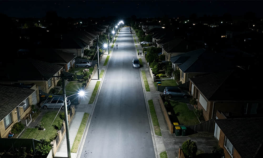
When a roadway lighting project is poorly planned, it can result in blinding glare for drivers, dangerous dark spots (often referred to as the "zebra effect" ), and a massive waste of lumens spilling into the night sky or adjacent properties. Conversely, a meticulously calculated arrangement guarantees superior road lighting uniformity, illuminating the pavement evenly to guide traffic safely while maximizing energy efficiency.
Achieving this perfect balance requires a deep understanding of multiple intersecting factors. In this comprehensive guide, we will break down the fundamental principles of street light layouts to help lighting engineers, urban planners, and project contractors make informed decisions. We will explore the five most common luminaire arrangement types, decode crucial design parameters such as pole spacing and mounting height, and examine the rigorous North American lighting standards (IESNA).
Furthermore, we will uncover the critical "core engine" behind every successful lighting layout: the secondary optical lens. As we will see, it is the precision engineering of these optics that ultimately dictates the light distribution, allowing the luminaire arrangement to seamlessly adapt to any road geometry.
Five Common Types of LED Street Light Luminaire Arrangement
The physical placement of street light poles relative to the roadway is the structural foundation of any lighting design. Selecting the correct luminaire layout configuration depends heavily on the width of the road, traffic volume, and municipal budgets. Generally, lighting engineers choose from five primary configurations:
1. Single-Sided Arrangement
In this layout, all street light poles are installed in a single line along one side of the road.
-
Best For: Narrow streets, residential roads, and pedestrian pathways.
-
Rule of Thumb: The road width should be equal to or less than the mounting height of the luminaire.
-
Pros & Cons: It is highly cost-effective and requires underground cabling on only one side of the street. However, if applied to roads that are too wide, the far side of the road will suffer from low luminance and poor visibility.
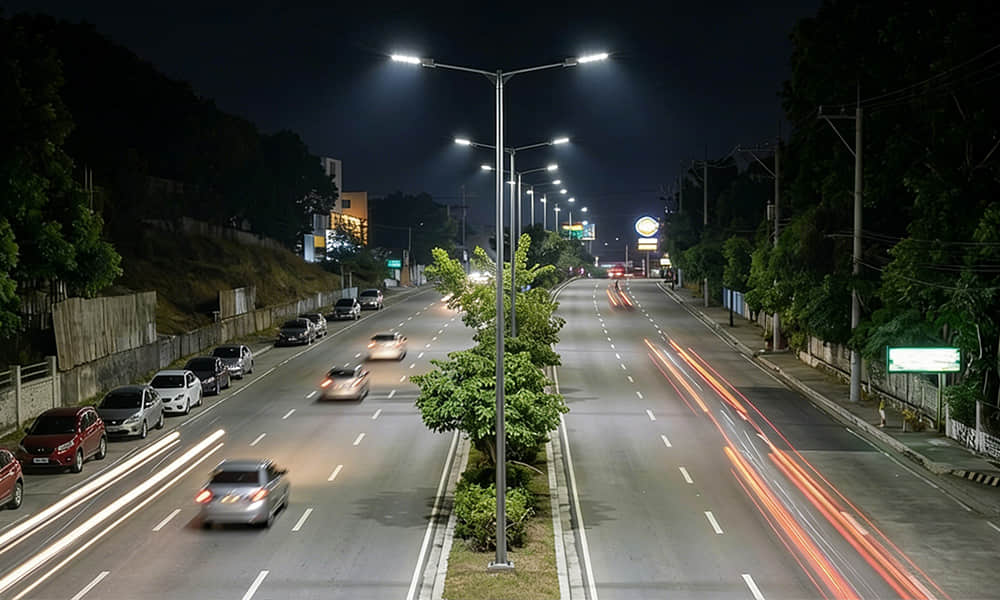
2. Staggered Arrangement
The staggered configuration places poles on both sides of the road, but they alternate in a zig-zag pattern.
-
Best For: Medium-width commercial roads and secondary arterial streets.
-
Rule of Thumb: Recommended when the road width is between 1 and 1.5 times the mounting height.
-
Pros & Cons: When comparing single sided vs staggered vs opposite arrangement, the staggered layout offers an excellent balance. It significantly improves longitudinal road lighting uniformity and minimizes the zebra effect without needing as many fixtures as an opposite layout. The drawback is that it requires trenching and cabling on both sides of the street.
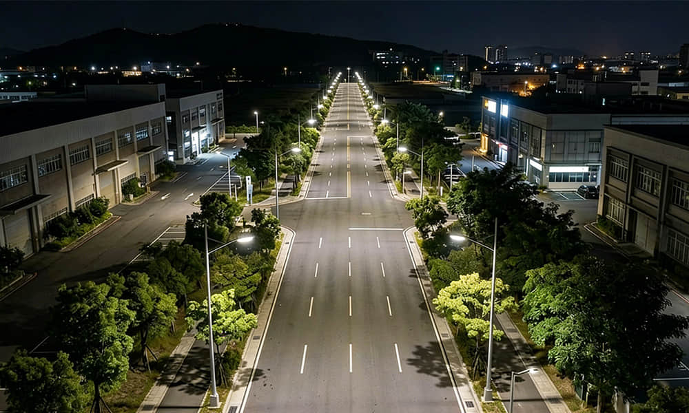
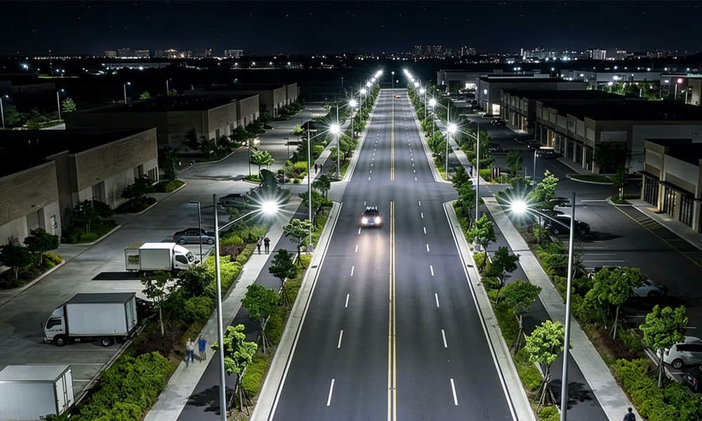
3. Opposite (Symmetric) Arrangement
In an opposite arrangement, luminaires are placed directly facing each other on both sides of the roadway.
-
Best For: Wide arterial roads, major multi-lane highways, and busy intersections.
-
Rule of Thumb: Necessary when the road width exceeds 1.5 times the mounting height.
-
Pros & Cons: This layout guarantees maximum brightness and the highest level of overall uniformity, ensuring extreme safety for heavy traffic. Unsurprisingly, it is also the most expensive configuration regarding initial installation and ongoing energy consumption.
4. Central Median Arrangement
Twin-arm street light poles are installed in the central median strip dividing a dual-carriageway.
-
Best For: Highways, expressways, and wide boulevards with a center divider.
-
Pros & Cons: Highly efficient, as a single pole infrastructure powers two luminaires illuminating opposite directions. It lowers the cost of pole installation and cabling. However, maintaining these lights often requires closing the fast lanes, which can disrupt traffic flow.
5. Overhanging (Cantilever) Arrangement
Luminaires are suspended directly over the center or edge of the roadway using long bracket arms, tension wires, or catenary systems.
-
Best For: Narrow historic districts, tree-lined streets, or urban areas where sidewalk space is too restricted for traditional pole bases.
-
Pros & Cons: Provides excellent center-road illumination and bypasses obstacles like dense tree canopies. However, the structural installation is complex, and the system can be susceptible to wind sway.
Key Design Parameters for Street Light Arrangement
Selecting the layout pattern is only the first step. To guarantee optimal road lighting uniformity and efficiency, engineers must precisely calculate the physical geometry of the installation. A successful LED street light arrangement hinges on four critical design parameters:
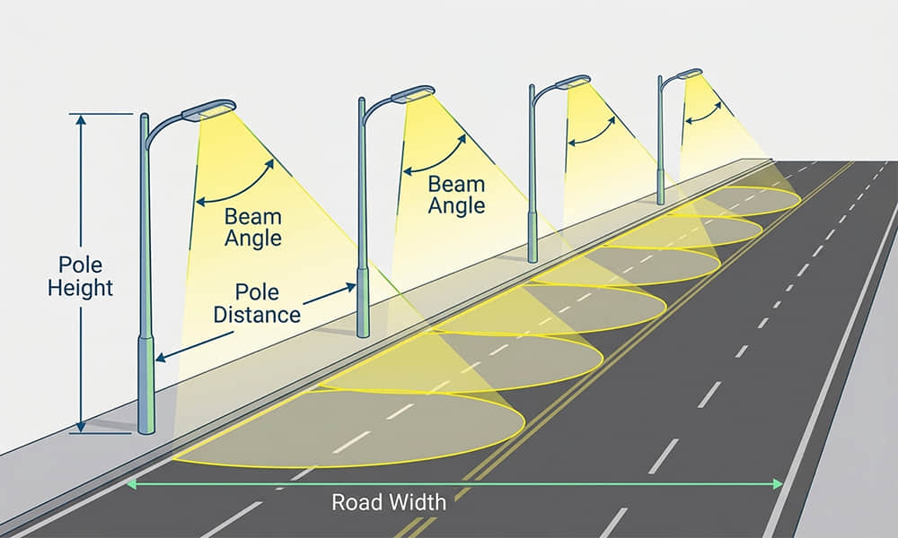
1. Pole Mounting Height
The mounting height of the luminaire is arguably the most influential factor in your design. It directly dictates the spread of the light and the potential for glare.
-
A lower mounting height increases the intensity of light on the ground but narrows the coverage area, often leading to glare for drivers.
-
A higher mounting height spreads the light over a larger area, resulting in a softer, more uniform distribution, but requires a higher-wattage LED fixture to maintain the required lux levels.
-
General Guidelines: 4 to 6 meters is typical for pedestrian pathways and residential streets; 8 to 12 meters is standard for commercial and arterial roads; and 15 meters or more is reserved for highway interchanges (high-mast lighting).
2. Pole Spacing and the S/H Ratio
Pole spacing is the longitudinal distance between two consecutive street lights. In lighting design, this is often calculated using the Spacing-to-Height (S/H) ratio. The street light spacing formula conceptually relies on this ratio to maintain uniformity. For most modern LED street lights equipped with quality optics, an S/H ratio of 3:1 to 4:1 is standard. For example, if your mounting height is 10 meters, a 3:1 ratio dictates a pole spacing of 30 meters. Pushing the spacing too far beyond the optic's capability will immediately result in dark patches between poles.
3. Overhang Distance
The overhang (or outreach) is the horizontal distance from the edge of the curb to the center of the luminaire, achieved via the bracket arm. An appropriate overhang—typically between 0.5 to 1.5 meters—helps push the light center directly over the active traffic lanes, bypassing obstacles like parked cars or overhanging tree branches. However, excessive overhang can reduce the illumination on the sidewalks and curbs, compromising pedestrian safety.
4. Tilt Angle (Boom Angle)
The tilt angle refers to the upward angle of the luminaire relative to the horizontal plane of the road. While tilting a fixture upward can push light further across a wide road, it is generally discouraged in modern lighting design. High tilt angles drastically increase blinding glare for approaching drivers and contribute heavily to light pollution (sky glow). Best practices and dark-sky compliance regulations recommend keeping the tilt angle as close to 0° (flat) as possible, relying instead on the fixture's internal secondary optical lens to direct the light where it is needed.
North American Standards & Road Lighting Uniformity (IESNA RP-8)
A well-arranged street lighting system must not only provide adequate brightness but also distribute that light consistently across the pavement. Globally, standards like the CIE road lighting standards often use metrics such as U0 (Overall Uniformity) and Ul (Longitudinal Uniformity) to evaluate this. However, for projects in or influenced by the North American market, engineers must strictly adhere to the guidelines set forth by the Illuminating Engineering Society of North America, specifically the IESNA RP-8 (Recommended Practice for Design and Maintenance of Roadway and Parking Facility Lighting).
Instead of just looking at raw lux levels, the IESNA RP-8 standard places a massive emphasis on luminance (the light reflecting off the road surface into the driver's eyes) and strict uniformity ratios to ensure visual comfort and safety.
To evaluate road lighting uniformity, IESNA primarily focuses on two critical ratios:
-
Average-to-Minimum Ratio: This metric compares the average light level on the road to the darkest spot. For major arterial roadways, a common standard is a 3:1 ratio (meaning the average brightness is no more than three times brighter than the darkest spot). For residential or local roads, a 6:1 ratio might be acceptable. This ensures that no area is dangerously under-illuminated.
-
Maximum-to-Minimum Ratio: This limits the intensity of the brightest hot spot directly under the pole compared to the darkest area. Extreme bright spots force the human eye's pupils to constantly dilate and constrict as a driver travels down the road, causing severe visual fatigue.
Why Uniformity Saves Lives
When street lights are spaced too far apart or improperly arranged, it creates alternating pools of bright light and deep shadows—a phenomenon known as the "zebra effect." This inconsistency acts as a camouflage for hazards, pedestrians, and potholes. By adhering to IESNA RP-8 uniformity standards, engineers ensure a seamless, continuous ribbon of light that significantly reduces driver reaction time and lowers nighttime accident rates.
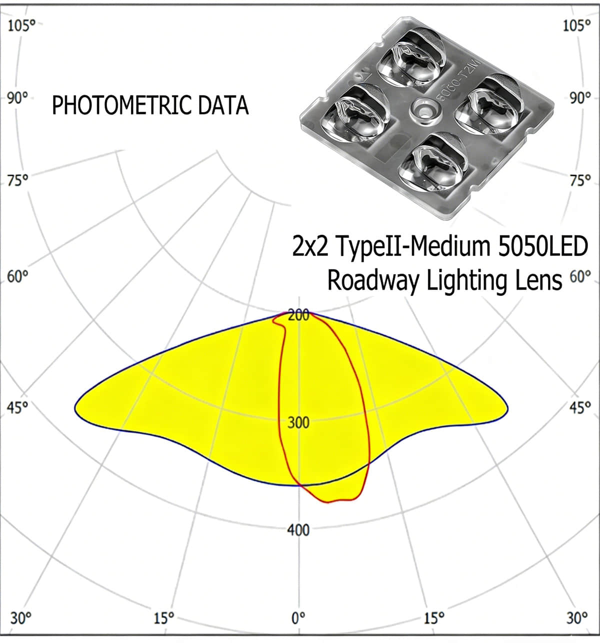
The Critical Role of Optical Lenses (IES Distribution Types)
While pole height and spacing are essential structural decisions, the true "magic" of a successful street light arrangement happens inside the luminaire itself. To push poles further apart (saving on infrastructure costs) without creating dark spots or tilting the fixture (which causes severe glare), engineers rely entirely on the secondary optical lens.
Instead of emitting light in a simple, uncontrolled circle, precision secondary optics reshape the LED's output into specific geometric patterns. In North America, the Illuminating Engineering Society (IES) categorizes these light distributions into five main types, depending on how the lens throws the light across and down the road:
-
Type I: A narrow, bilateral distribution ideal for pathways or walkways where the luminaire is placed precisely in the center.
-
Type II: Features a slightly wider, asymmetrical forward throw. It is the industry standard for illuminating typical two-lane municipal roads and wide walkways.
-
Type III: Provides a much wider forward throw, making it perfect for medium-to-wide arterial roads, often used in staggered or single-sided arrangements where the light needs to reach across multiple lanes.
-
Type IV: Known as a "forward throw" distribution, it pushes light deeply across wide highways or large parking areas with minimal back-light.
-
Type V: A symmetrical, 360-degree circular or square distribution, generally used in the center of intersections or large open plazas.
Selecting the Right Lens for Your Arrangement
The choice of lens distribution directly dictates your layout configuration. For example, if you are working on a standard two-lane roadway project, utilizing a highly efficient Type II lens is critical to maximizing the pole spacing while strictly maintaining IESNA uniformity standards. For such applications, the 2x2 T2M (Type II Medium) lens engineered by Asahi Optics stands out. Designed specifically for 5050 LEDs, this lens offers exceptional directional light control, ensuring maximum lumen efficiency and perfect medium-throw illumination without unwanted light spill.
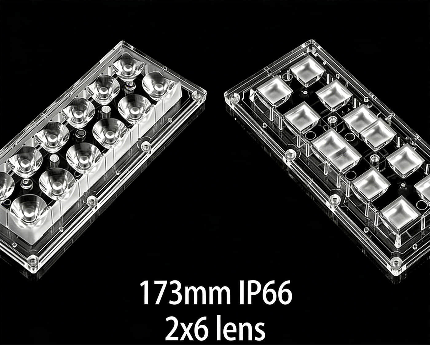
As road widths increase or traffic classifications demand higher wattages, lighting manufacturers often transition to modular luminaire designs. For wide arterial roads requiring robust Type III or Type IV setups, scalable optics are required. The 2x6 Lens Series (LP66) provides extreme versatility for these complex roadway layouts. By utilizing these modular, highly transmissive lenses, lighting fixture manufacturers can seamlessly scale up the power and adapt the distribution pattern to perfectly match any staggered or opposite pole arrangement.
Design Tools for Luminaire Arrangement Validation
Even with a deep understanding of pole spacing, IES distribution types, and uniformity standards, professional lighting engineers never rely on guesswork. To guarantee that a proposed LED street light arrangement will meet all safety and performance criteria before a single pole is installed in the ground, designers use advanced photometric simulation software.
The two most prominent software programs used globally are DIALux (widely used in Europe and Asia) and AGi32 (the industry standard in North America for IESNA compliance).
The standard workflow for validating a luminaire arrangement is straightforward:
-
Define the Roadway: Input the exact physical parameters of the project, including road width, number of lanes, median size, and pedestrian pathways.
-
Import IES Files: Load the specific .ies files provided by the luminaire or lens manufacturer. These files contain the exact photometric data (the 3D light distribution curve) of the chosen fixture.
-
Configure the Layout: Set the proposed arrangement type (e.g., staggered or single-sided), pole height, overhang, tilt angle, and pole spacing.
-
Run the Simulation: The software calculates millions of light rays interacting with the defined pavement surface.
-
Analyze the Results: The program outputs a detailed report showing the average illuminance (lux/footcandles), overall uniformity, and maximum-to-minimum ratios. If the layout fails to meet the required IESNA standards, the designer can quickly iterate by adjusting the spacing, changing the pole height, or selecting a different optical lens (e.g., switching from a Type II to a Type III distribution) until perfect compliance is achieved.
Conclusion: Good Arrangement Starts with Good Optics
Designing the perfect LED street light luminaire arrangement is a rigorous balancing act. While physical parameters like pole height, spacing, and layout configuration form the skeleton of the lighting system, it is the optical precision that serves as the heart.
As we have explored, simply placing poles closer together or raising them higher is not an efficient way to achieve road lighting uniformity. True performance relies on strictly adhering to IESNA standards and selecting the exact IES distribution type for your specific road geometry. By prioritizing high-quality, perfectly engineered secondary optical lenses—such as the precision Type II and modular 2x6 arrays from Asahi Optics—lighting contractors and fixture manufacturers can confidently deliver safe, uniform, and highly energy-efficient roadways for any municipality.
FAQ: Frequently Asked Questions About Street Light Arrangement
Q: What is the ideal Spacing-to-Height (S/H) ratio for LED street lights?
A: While it depends heavily on the specific optical lens used, a standard S/H ratio for modern LED street lighting falls between 3:1 and 4:1. For example, a 10-meter pole would typically be spaced 30 to 40 meters apart from the next pole. Pushing the ratio to 5:1 is possible but requires highly specialized wide-distribution optics to avoid dark spots.
Q: How do I choose between a Type II and Type III IES distribution?
A: The choice depends on the width of the area you need to illuminate. Type II distributions are relatively narrow and are ideal for standard two-lane streets or wide pathways where the light needs to be pushed longitudinally down the road. Type III distributions provide a wider forward throw, making them the better choice for multi-lane arterial roads where the light must reach across several lanes from a side-mounted pole.
Q: How can I fix uneven street lighting (the "zebra effect") if the poles are already installed?
A: If the infrastructure (poles and wiring) is already in the ground, relocating the poles to reduce spacing is usually cost-prohibitive. The most effective and economical solution is to retrofit the luminaire head. By upgrading to an LED fixture equipped with a high-performance secondary optical lens designed for a wider light distribution (such as moving to a more aggressive Type III or Type IV lens), you can stretch the light further down the road, overlapping the beams to eliminate the dark spots and restore uniformity.